


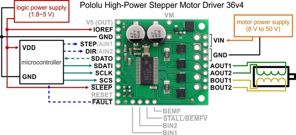
This discrete MOSFET stepper motor driver enables control of one bipolar stepper motor. It supports a wide 8 V to 50 V operating voltage range and can deliver up to 4 A continuous per phase without a heat sink or forced air flow (6 A max with sufficient additional cooling). The SPI interface allows configuration of the current limiting, step mode (9 step modes from full-step through 1/256-step), decay mode, and stall detection. The driver also provides back-EMF feedback that can be used for more advanced control and stall detection algorithms. Additional features include reverse-voltage, under-voltage, and over-current protection.
- Wide 8 V to 50 V operating voltage range
- High-power: can deliver up to 4 A continuous per phase without extra cooling (6 A max with sufficient additional cooling)
- Highly configurable through SPI interface
- Optional STEP/DIR control pins (stepping can also be controlled through SPI interface alone)
- Nine different step resolutions down to 256 microsteps: full-step, half-step, 1/4-step, 1/8-step, 1/16-step, 1/32-step, 1/64-step, 1/128-step, and 1/256-step
- Adjustable current control lets you set the maximum current output, enabling the use of voltages above your stepper motor’s rated voltage to achieve higher step rates
- Adaptive blanking time, adjustable decay times, and various current decay modes enable the creation of ultra-smooth motion profiles through the SPI interface
- Optional STALL output enables stall detection when microstepping
- Optional BEMF output enables more advanced control and stall detection algorithms based on the back EMF of the stepper motor
- Driver supports alternate operating mode for controlling two brushed DC motors with PWM inputs instead of one bipolar stepper motor with STEP/DIR inputs
- Inputs compatible with 1.8 V, 3.3 V, and 5 V logic
- Digital outputs are all open drain with pull-ups to externally supplied IOREF voltage for use with non-5V systems (IOREF can be connected to neighboring 5V OUT pin for use with 5V systems)
- Under-voltage lockout, over-current protection, short circuit protection, and reverse-voltage protection (up to 40 V)
- Arduino library and example sketches are available that provide basic functions for configuring and operating the driver
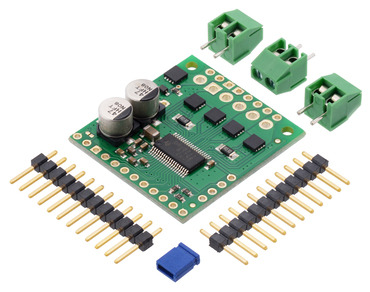
- Two 1×12-pin breakaway 0.1″ male header
- Three 2-pin, 3.5 mm terminal blocks (for board power and motor outputs)
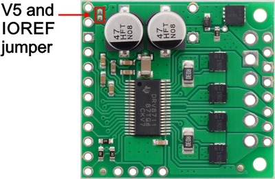
- One 0.1″ shorting block (for optionally connecting IOREF to neighboring V5 pin when using this driver in 5 V systems)
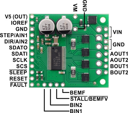
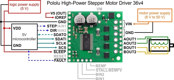
| PIN | Description |
|---|---|
| VIN | 8 V to 50 V board power supply connection (reverse-protected up to 40 V). |
| VM | This pin gives access to the motor power supply after the reverse-voltage protection MOSFET (see the board schematic at the bottom of this page). It can be used to supply reverse-protected power to other components in the system. This pin can also be used with the adjacent GND pin to add an external electrolytic capacitor in systems where additional bypass capacitance would be helpful. |
| GND | Ground connection points for the motor power supply and control ground reference. The control source and the motor driver must share a common ground. |
| AOUT1 | Motor output: “positive” end of phase A coil. |
| AOUT2 | Motor output: “negative” end of phase A coil. |
| BOUT1 | Motor output: “positive” end of phase B coil. |
| BOUT2 | Motor output: “negative” end of phase B coil. |
| V5 (OUT) | Regulated 5 V output: this pin gives access to the voltage from the internal regulator of the DRV8711. The regulator can only provide up to 10 mA, so it is primarily only useful for hard-wiring board inputs high and powering pull-ups for the board’s open-drain outputs. It is generally not intended for powering external devices. |
| IOREF | All of the board signal outputs (except BEMF) are open-drain outputs that are pulled up to IOREF, so this pin should be supplied with the logic voltage of the controlling system (e.g. 3.3 V for use in 3.3 V systems). For convenience, it can be connected to the neighboring V5 (OUT) pin when it is being used in a 5 V system. |
| STEP/AIN1 | Changes on this input move the motor current one step up or down in the translator table (even when the motor is disabled). Stepping can also be controlled through the SPI interface, so this pin is optional. In external PWM mode, this pin functions as AIN1 rather than STEP and directly controls the state of the AOUT1 output. |
| DIR/AIN2 | Input that determines the direction of stepper motor rotation. The direction can also be controlled through the SPI interface, so this pin is optional. In external PWM mode, this pin functions as AIN2 rather than DIR and directly controls the state of the AOUT2 output. |
| SDATO | SPI data output. (This pin is also often referred to as “MISO”.) This pin is an open-drain output and is pulled up to IOREF on the board. |
| SDATI | SPI data input. (This pin is also often referred to as “MOSI”.) |
| SCLK | SPI clock input. |
| SCS | SPI chip select input. Logic transitions on this pin are required for SPI communication, even if this is the only device on the SPI bus. |
| SLEEP | By default, the driver pulls this pin low, which puts it in a low-power sleep mode where the motor driver circuitry is disabled and all analog circuitry is placed into a low-power state. The digital circuitry still operates in sleep mode, so the device registers can still be accessed via the serial interface. This pin must be driven high to enable the device. |
| RESET | Chip reset input. A logic high on this input resets all internal logic, including the indexer and device registers, and disables the driver outputs. Note: the RESET pin does not function while the device is in sleep mode. |
| FAULT | Open-drain output that drives low when an over-current, pre-driver, over-temperature, or under-voltage fault is occurring. This pin is pulled up to IOREF, making it high by default. |
| BIN1 | In external PWM mode, BIN1 directly controls the state of the BOUT1 output. This pin is not used in indexer mode (i.e. when using this device as a stepper motor driver). |
| BIN2 | In external PWM mode, BIN2 directly controls the state of the BOUT2 output. This pin is not used in indexer mode (i.e. when using this device as a stepper motor driver). |
| STALL/BEMFV | Open-drain output that is pulled up to IOREF on the board. In internal stall detect mode, output goes low when stall is detected. In external stall detect mode, output goes low when valid back EMF measurement is available. |
| BEMF | Analog output that represents the motor back EMF. The signal on this pin can be further processed by a microcontroller to implement more advanced control and stall detection algorithms. |

Related Products

Pololu 2973 / 2974 / 2998 Stepper Motor Driver Carrier TB67S249FTG/ TB67S279FTG/ TB67S128FTG
This breakout board makes it easy to use Toshiba’s TB67S249FTG/ TB67S279FTG microstepping bipolar st..
रo 1,044.90

Pololu 2878 / 2879 STSPIN820 Stepper Motor Driver Carrier
This breakout board for STMicro’s STSPIN820 microstepping bipolar stepper motor driver offers micros..
रo 2,024.49

Pololu 3098 / 3099 Stepper Motor Driver Compact Carrier TB67S279FTG
This breakout board for Toshiba’s TB67S279FTG microstepping bipoloar stepper motor driver is arrange..
रo 963.67

Pololu 3096 / 3097 Stepper Motor Driver Compact Carrier TB67S249FTG
This breakout board for Toshiba’s TB67S249FTG microstepping bipoloar stepper motor driver is arrange..
रo 1,142.74

Pololu 2876 / 2877 STSPIN220 Low-Voltage Stepper Motor Driver Carrier
This breakout board for STMicro’s STSPIN220 low-voltage microstepping bipolar stepper motor driver o..
रo 897.41

Pololu 3731 High-Power Stepper Motor Driver 36v8
This discrete MOSFET stepper motor driver enables control of one bipolar stepper motor. It supports ..
रo 2,704.68