

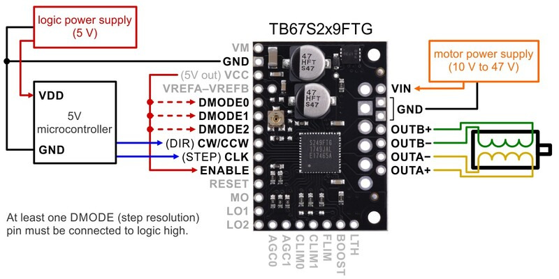
This breakout board makes it easy to use Toshiba’s TB67S249FTG/ TB67S279FTG microstepping bipolar stepper motor driver, which features adjustable current limiting and seven microstep resolutions (down to 1/32-step). In addition, it dynamically selects an optimal decay mode by monitoring the actual motor current, and it can automatically reduce the driving current below the full amount when the motor is lightly loaded to minimize power and heat. The TB67S249FTG has a wide operating voltage range of 10 V to 47 V and can deliver approximately 1.7 A/ 1.2 A respectively per phase continuously without a heat sink or forced air flow (up to 4.5 A peak). It features built-in protection against under-voltage, over-current, and over-temperature conditions; our carrier board also adds reverse-voltage protection (up to 40 V).
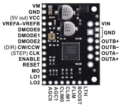
TB67S2x9FTG Stepper Motor Driver Carrier, top view with labeled pinout.
| PIN | Default Value | Description |
| VIN | 10 V to 47 V board power supply connection (reverse-protected up to 40 V). | |
| GND | Ground connection points for the motor power supply and control ground reference. The control source and the motor driver must share a common ground. | |
| VM | This pin gives access to the motor power supply after the reverse-voltage protection MOSFET (see the board schematic below). It can be used to supply reverse-protected power to other components in the system. It is generally intended as an output, but it can also be used to supply board power. | |
| A+ | Motor A output: “positive” end of phase A coil. | |
| A− | Motor output: “negative” end of phase A coil. | |
| B+ | Motor output: “positive” end of phase B coil. | |
| B− | Motor output: “negative” end of phase B coil. | |
| VCC | Regulated 5 V output: this pin gives access to the voltage from the internal regulator of the TB67S2x9FTG. The regulator can only provide a few milliamps, so the VCC output should only be used for logic inputs on the board (such as the neighboring DMODE pins), not for powering external devices. | |
|
VREFA,
VREFB
|
Voltage reference pins for setting the current limit. By default, these pins are connected to the potentiometer and to each other so that the current limit is the same on both channels, but you can cut the trace between them to set the current limit for each motor channel separately. | |
|
DMODE0,
DMODE1,
DMODE2
|
LOW | Step resolution selection pins. These pins are all pulled low by default, putting the driver into a low-power standby mode and disabling the outputs; at least one DMODE pin must be driven high to set the step resolution and and allow the driver to operate. |
| CW/CCW (DIR) | LOW | Input that determines the direction of rotation. |
| CLK (STEP) | LOW | A rising edge on this input causes the driver to advance the motor by one step or microstep (moving the coil currents one step up or down in the translator table). |
| ENABLE | LOW | Enable input. By default, the driver pulls this pin low, disabling the motor outputs; it must be driven high to enable the driver. |
| RESET | LOW | Reset input: driving this pin high resets the driver’s internal electrical angle (the state in the translator table that it is outputting). |
| MO | This open-drain output is low when the driver’s internal electrical angle is at its initial value (the value after reset); otherwise, the board pulls it up to VCC. | |
|
LO1,
LO2
|
HIGH | Error outputs: these pins drive low to indicate that an error condition has occurred; otherwise, the board pulls them up to VCC. The specific error can be determined by the state of both error pins. |
|
AGC0,
AGC1
|
HIGH | These inputs determine whether Active Gain Control (AGC) is enabled. AGC0 should not be changed while the driver is operating. See the datasheet and the Active Gain Control section below for details about the AGC feature. |
|
CLIM0,
CLIM1
|
HIGH,
100 kΩ
pull-up
|
These inputs set the bottom (minimum) current limit when AGC is active. CLIM1 is a four-state input. |
| FLIM |
100 kΩ
pull-up
|
This four-state input sets the bottom frequency limit (minimum step rate) for AGC to be active. |
| BOOST |
100 kΩ
pull-up
|
This four-state input determines how quickly the motor current is boosted back to the normal limit after the driver detects increased load torque with AGC active. |
| LTH |
100 kΩ
pull-down
|
This input controls the AGC detection threshold (torque detection sensitivity). |
Pololu 2973 / 2974 / 2998 Stepper Motor Driver Carrier TB67S249FTG/ TB67S279FTG/ TB67S128FTG
- Brand:: Pololu
- Product Code: :Pololu-Stepper-Motor-Driver-Carrier
- Reward Points: :10
- Availability: :In Stock
-
रo 1,044.90
- Price in reward points: 1045
-
- 25 or more रo 875.68
- 100 or more रo 842.57
Available Options
Related Products

Pololu 2990 DRV8838 Single Brushed DC Motor Driver Carrier
This tiny breakout board for TI’s DRV8838 motor driver can deliver a continuous 1.7 A (1.8 A peak) t..
रo 405.76

Pololu 2961 MAX14870 Single Brushed DC Motor Driver Carrier
This compact breakout board for Maxim’s MAX14870 motor driver offers a wide operating voltage range ..
रo 979.21

Pololu 2960 BD65496MUV Single Brushed DC Motor Driver Carrier
This compact breakout board for ROHM’s BD65496MUV motor driver offers an operating voltage range of ..
रo 1,233.82

Pololu 2999 TB67H420FTG Dual/Single Motor Driver Carrier
The TB67H420FTG from Toshiba is an H-bridge motor driver IC that can be used for bidirectional contr..
रo 1,061.22

Pololu 2878 / 2879 STSPIN820 Stepper Motor Driver Carrier
This breakout board for STMicro’s STSPIN820 microstepping bipolar stepper motor driver offers micros..
रo 2,024.49

Pololu 3730 High-Power Stepper Motor Driver 36v4
This discrete MOSFET stepper motor driver enables control of one bipolar stepper motor. It supports ..
रo 2,044.30
Tags: Pololu, Stepper, Motor, Driver, Carrier TB67S249FTG TB67S279FTG