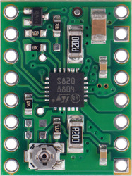
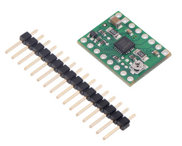
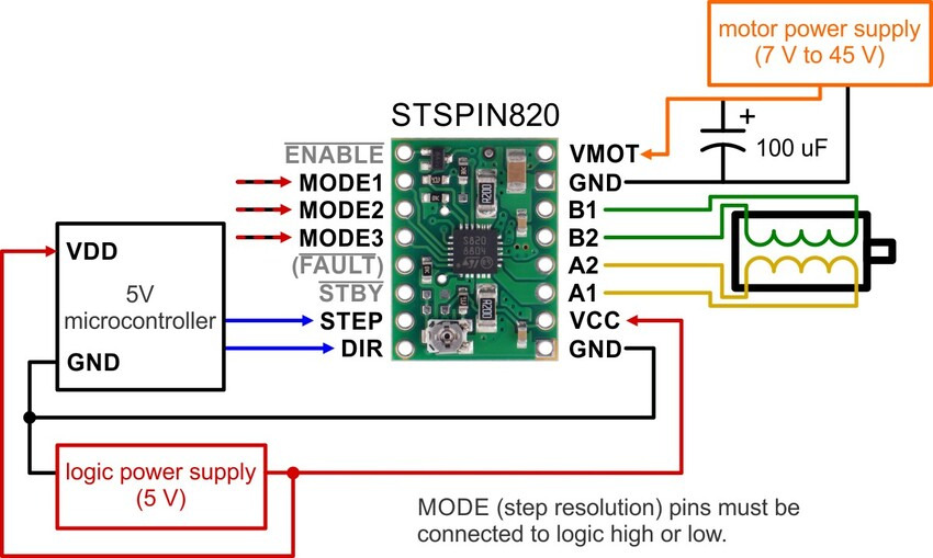
This breakout board for STMicro’s STSPIN820 microstepping bipolar stepper motor driver offers microstepping down to 1/256-step and a wide operating range of 7 V to 45 V. It can deliver up to approximately 0.9 A per phase continuously without a heat sink or forced air flow (up to 1.5 A peak). The module has a pinout and interface that are very similar to that of our popular A4988 carriers, so it can be used as a drop-in replacement for those boards in many applications.

Overview

This product is a carrier board or breakout board for the STSPIN820 stepper motor driver from STMicroelectronics (ST); we therefore recommend careful reading of the STSPIN820 datasheet (594k pdf) before using this product. This stepper motor driver offers microstep resolutions down to 1/256 of a step, and it lets you control one bipolar stepper motor at up to approximately 0.9 A per phase continuously without a heat sink or forced air flow (see the Power dissipation considerations section below for more information). Here are some of the driver’s key features:
 
Simple step and direction control interface
Eight different step resolutions down to 256 microsteps: full-step, half-step, 1/4-step, 1/8-step, 1/16-step, 1/32-step, 1/128-step, and 1/256-step
Adjustable current control lets you set the maximum current output, which lets you use voltages above your stepper motor’s rated voltage to achieve higher step rates
Motor supply voltage: 7 V to 45 V
Can deliver 0.9 A per phase continuously without additional cooling
Can interface directly with 3.3 V and 5 V systems
Over-temperature thermal shutdown, over-current shutdown, and short circuit protection
4-layer, 2 oz copper PCB for improved heat dissipation
Exposed solderable ground pad below the driver IC on the bottom of the PCB
Module size, pinout, and interface match those of our A4988 stepper motor driver carriers in most respects
 
This product ships with all surface-mount components—including the STSPIN820 driver IC—installed as shown in the product picture


Included hardware
 
The STSPIN820 stepper motor driver carrier ships with one 1×16-pin breakaway 0.1″ male headers (for a version of this carrier with header pins already installed, see item #2879). The headers can be soldered in for use with solderless breadboards or 0.1″ female connectors. You can also solder your motor leads and other connections directly to the board.


Using the driver


Power connections
 
The driver requires a logic supply voltage (3 – 5 V) to be connected across the VCC and GND pins and a motor supply voltage of 7 V to 45 V to be connected across VIN and GND. These supplies should have appropriate decoupling capacitors close to the board, and they should be capable of delivering the expected currents (peaks up to 3 A for the motor supply).
 
Motor connections
 
The STSPIN820 is intended to control a single bipolar stepper motor. The two sides of one coil should be connected across OUTA1 and OUTA2, and the two sides of the other coil should be connected across OUTB1 and OUTB2.
 
Warning: Connecting or disconnecting a stepper motor while the driver is powered can destroy the driver. (More generally, rewiring anything while it is powered is asking for trouble.)
 
Step (and microstep) size
 
Stepper motors typically have a step size specification (e.g. 1.8° or 200 steps per revolution), which applies to full steps. A microstepping driver such as the STSPIN820 allows higher resolutions by allowing intermediate step locations, which are achieved by energizing the coils with intermediate current levels. For instance, driving a motor in quarter-step mode will give the 200-step-per-revolution motor 800 microsteps per revolution by using four different current levels.
 
The resolution (step size) selector inputs (MODE1, MODE2, and MODE3) enable selection from the eight step resolutions according to the table below. These three pins are floating, so the MODE pins must be connected to logic high or low before operating the driver. For the microstep modes to function correctly, the current limit must be set low enough (see below) so that current limiting gets engaged. Otherwise, the intermediate current levels will not be correctly maintained, and the motor will skip microsteps.
 

MODE1

MODE2

MODE3

Microstep Resolution

Low

Low

Low

Full step

High

Low

Low

Half step

Low

High

Low

1/4 step

High

High

Low

1/8 step

Low

Low

High

1/16 step

High

Low

High

1/32 step

Low

High

High

1/128 step

High

High

High

1/256 step


Control inputs and status outputs
 
The rising edge of each pulse to the STEP (STCK) input corresponds to one microstep of the stepper motor in the direction selected by the DIR pin. Unlike most of our other stepper motor driver carriers, the STEP and DIR inputs are floating, so they must be connected to logic high or low to ensure proper operation.
 
The STSPIN820 IC has two different inputs for controlling its power states, STBY/RESET and EN/FAULT:
 
When the STBY pin is driven low, the driver enters a low-power mode, disables the motor outputs, and resets the translation table. We call this pin STBY on our board based on the logic of how it works, but it is a direct connection to the STBY pin on the driver.
The EN pin is inverted by our carrier board and presented as ENABLE, which makes it the same way as the enable pins on our various other stepper motor drivers with this form factor. It is pulled low on the board to enable the driver by default, and it can be driven low to disable the outputs.
The STSPIN820 can detect several fault (error) states that it reports by driving EN/FAULT pin on the driver low. The FAULT pin is not made available by default (to avoid conflicts when using the STSPIN820 carrier as a drop-in replacement for our other stepper motor driver carriers), but it can be connected to the pin labeled “( FLT )” by bridging the surface mount jumper labeled “F” on the bottom side of the board.
 
On our carrier, the DECAY input is pulled down with a 10k resistor that sets the driver to mixed decay mode. The driver can be set to slow decay mode by bridging the surface mount jumper labeled “D” on the bottom side of the board.


To achieve high step rates, the motor supply is typically higher than would be permissible without active current limiting. For instance, a typical stepper motor might have a maximum current rating of 1 A with a 5 Ω coil resistance, which would indicate a maximum motor supply of 5 V. Using such a motor with 10 V would allow higher step rates, but the current must actively be limited to under 1 A to prevent damage to the motor.
 
The STSPIN820 supports such active current limiting, and the trimmer potentiometer on the board can be used to set the current limit. You will typically want to set the driver’s current limit to be at or below the current rating of your stepper motor. One way to set the current limit is to put the driver into full-step mode and to measure the current running through a single motor coil without clocking the STEP input. The measured current will be equal to the current limit (since both coils are always on and limited to 100% of the current limit setting in full-step mode).
 
Another way to set the current limit is to measure the VREF voltage and calculate the resulting current limit. The current limit relates to VREF as follows:
 
current limit=VREF×5 AV
 
Note: The coil current can be very different from the power supply current, so you should not use the current measured at the power supply to set the current limit. The appropriate place to put your current meter is in series with one of your stepper motor coils. If the driver is in full-step mode, both coils will always be on and limited to 100% of the current limit setting as (unlike some other drivers that limit it to about 70% in full-step mode). If your driver is in one of the microstepping modes, the current through the coils will change with each step, ranging from 0% to 100% of the set limit.
 
Power dissipation considerations
 
The driver ICs have maximum current ratings higher than the continuous currents we specify for these carrier boards, but the actual current you can deliver depends on how well you can keep the IC cool. The carrier’s printed circuit board is designed to draw heat out of the IC, but to supply more than the specified continuous current per coil, a heat sink or other cooling method is required.
 
This product can get hot enough to burn you long before the chip overheats. Take care when handling this product and other components connected to it.
 
Please note that measuring the current draw at the power supply will generally not provide an accurate measure of the coil current. Since the input voltage to the driver can be significantly higher than the coil voltage, the measured current on the power supply can be quite a bit lower than the coil current (the driver and coil basically act like a switching step-down power supply). Also, if the supply voltage is very high compared to what the motor needs to achieve the set current, the duty cycle will be very low, which also leads to significant differences between average and RMS currents. Additionally, please note that the coil current is a function of the set current limit, but it does not necessarily equal the current limit setting as the actual current through each coil changes with each microstep and can be further reduced if Active Gain Control is active.
 
Schematic diagram


Write a review

Please login or register to review

Pololu 2878 / 2879 STSPIN820 Stepper Motor Driver Carrier

  • Brand: Pololu
  • Product Code:Pololu-STSPIN820-Stepper-Motor-Driver-Carrier
  • Reward Points:16
  • Availability:In Stock
  • रo 1,882.10

  • Ex Tax:रo 1,595.00
  • Price in reward points:1595

  • 10 or more रo 1,867.94
  • 20 or more रo 1,852.60
  • 50 or more रo 1,837.26
  • 100 or more रo 1,821.92

Available Options


Related Products

Pololu 2134 / 2874 DRV8834 Low-Voltage Stepper Motor Driver Carrier

Pololu 2134 / 2874 DRV8834 Low-Voltage Stepper Motor Driver Carrier

This is a breakout board for TI’s DRV8834 microstepping bipolar stepper motor driver. It has a pinou..

रo 767.00 Ex Tax:रo 650.00

Pololu 1212 MC33926 Motor Driver Carrier

Pololu 1212 MC33926 Motor Driver Carrier

This breakout board for Freescale’s MC33926 full H-bridge has an operating range of 5 – 28 V and can..

रo 4,401.40 Ex Tax:रo 3,730.00

Pololu 2130 DRV8833 Dual Motor Driver Carrier

Pololu 2130 DRV8833 Dual Motor Driver Carrier

This tiny breakout board for TI’s DRV8833 dual motor driver can deliver 1.2 A per channel continuous..

रo 1,504.50 Ex Tax:रo 1,275.00

Pololu 2135 DRV8835 Dual Motor Driver Carrier

Pololu 2135 DRV8835 Dual Motor Driver Carrier

This tiny breakout board for TI’s DRV8835 dual motor driver can deliver 1.2 A per channel continuous..

रo 479.08 Ex Tax:रo 406.00

Pololu 2137 A4990 Dual Motor Driver Carrier

Pololu 2137 A4990 Dual Motor Driver Carrier

This compact breakout board makes it easy to use Allegro’s A4990 dual motor driver, which can contro..

रo 767.00 Ex Tax:रo 650.00

Pololu 2999 TB67H420FTG Dual/Single Motor Driver Carrier

Pololu 2999 TB67H420FTG Dual/Single Motor Driver Carrier

The TB67H420FTG from Toshiba is an H-bridge motor driver IC that can be used for bidirectional contr..

रo 1,259.06 Ex Tax:रo 1,067.00

Pololu 2973 / 2974 / 2998 Stepper Motor Driver Carrier TB67S249FTG/ TB67S279FTG/ TB67S128FTG

Pololu 2973 / 2974 / 2998 Stepper Motor Driver Carrier TB67S249FTG/ TB67S279FTG/ TB67S128FTG

This breakout board makes it easy to use Toshiba’s TB67S249FTG/ TB67S279FTG microstepping bipolar st..

रo 1,296.82 Ex Tax:रo 1,099.00

Pololu 707/708 VNH2SP30/VNH3SP30 Dual Motor Driver Carrier MD03A 708 707

Pololu 707/708 VNH2SP30/VNH3SP30 Dual Motor Driver Carrier MD03A 708 707

The Pololu dual high-power motor drivers are compact carriers for the VNH3SP30 and VNH2SP30 motor dr..

रo 20,808.12 Ex Tax:रo 17,634.00

Pololu 3098 / 3099 Stepper Motor Driver Compact Carrier TB67S279FTG

Pololu 3098 / 3099 Stepper Motor Driver Compact Carrier TB67S279FTG

This breakout board for Toshiba’s TB67S279FTG microstepping bipoloar stepper motor driver is arrange..

रo 1,064.36 Ex Tax:रo 902.00

Pololu 3096 / 3097 Stepper Motor Driver Compact Carrier TB67S249FTG

Pololu 3096 / 3097 Stepper Motor Driver Compact Carrier TB67S249FTG

This breakout board for Toshiba’s TB67S249FTG microstepping bipoloar stepper motor driver is arrange..

रo 1,250.80 Ex Tax:रo 1,060.00

Pololu 2876 / 2877 STSPIN220 Low-Voltage Stepper Motor Driver Carrier

Pololu 2876 / 2877 STSPIN220 Low-Voltage Stepper Motor Driver Carrier

This breakout board for STMicro’s STSPIN220 low-voltage microstepping bipolar stepper motor driver o..

रo 767.00 Ex Tax:रo 650.00

Smart Electronics Kits NE555+CD4017 Light LED Module DIY Kit

Smart Electronics Kits NE555+CD4017 Light LED Module DIY Kit

Specification : Board size : 53mm*19mm Supply Voltage : 2.5 - 14 .5 ..

रo 100.30 Ex Tax:रo 85.00

Pololu 3138 / 3139 Tic T249 USB Multi-Interface Stepper Motor Controller

Pololu 3138 / 3139 Tic T249 USB Multi-Interface Stepper Motor Controller

The Tic T249 USB Multi-Interface Stepper Motor Controller makes basic control of a stepper motor eas..

रo 8,179.76 Ex Tax:रo 6,932.00

Pololu 3730 High-Power Stepper Motor Driver 36v4

Pololu 3730 High-Power Stepper Motor Driver 36v4

This discrete MOSFET stepper motor driver enables control of one bipolar stepper motor. It supports ..

रo 2,407.20 Ex Tax:रo 2,040.00

Pololu 2133 / 2982 DRV8825 Stepper Motor Driver Carrier, High Current

Pololu 2133 / 2982 DRV8825 Stepper Motor Driver Carrier, High Current

This breakout board for TI’s DRV8825 microstepping bipolar stepper motor driver features adjustable ..

रo 2,385.96 Ex Tax:रo 2,022.00

Tags: Pololu, Stepper, Motor, Driver, Carrier

The product is currently Out-of-Stock. Enter your email address below and we will notify you as soon as the product is available.

Name
Email
Phone
Comments