Stepper motors typically have a step size specification (e.g. 1.8° or 200 steps per revolution), which applies to full steps. A microstepping driver such as the STSPIN220 allows higher resolutions by allowing intermediate step locations, which are achieved by energizing the coils with intermediate current levels. For instance, driving a motor in quarter-step mode will give the 200-step-per-revolution motor 800 microsteps per revolution by using four different current levels.
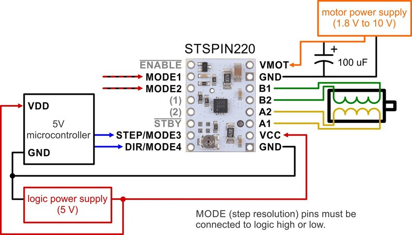
Unlike our other stepper motor drivers, some of the resolution (step size) selector inputs share pins with the STEP/STCK and DIR pins, and the values of the inputs are latched at power-up or when standby mode is released. After this, the values on the inputs do not affect the microstep mode, and the MODE3 and MODE4 inputs start operating as step and direction controls. The only exception is the case where MODE1 and MODE2 are both driven low, which overrides the latched microstep setting and forces the driver into full-step mode. The previous microstep setting is restored once MODE1 or MODE2 is set high.
There are nine step resolutions available as shown in the table below. The four MODE pins are floating, so they must be connected to logic high or low before operating the driver. For the microstep modes to function correctly, the current limit must be set low enough (see below) so that current limiting gets engaged. Otherwise, the intermediate current levels will not be correctly maintained, and the motor will skip microsteps.
|
MODE1
|
MODE2
|
MODE3 (STEP)
|
MODE4 (DIR)
|
Latched step setting
|
|
Low
|
Low
|
Low
|
Low
|
Full step
|
|
High
|
Low
|
High
|
Low
|
Half step
|
|
Low
|
High
|
Low
|
High
|
1/4 step
|
|
High
|
High
|
High
|
Low
|
1/8 step
|
|
High
|
Low
|
High
|
High
|
1/8 step
|
|
High
|
High
|
High
|
High
|
1/16 step
|
|
Low
|
High
|
Low
|
Low
|
1/32 step
|
|
Low
|
Low
|
Low
|
High
|
1/32 step(1)
|
|
High
|
High
|
Low
|
High
|
1/64step
|
|
Low
|
High
|
High
|
High
|
1/64 step
|
|
High
|
Low
|
Low
|
Low
|
1/128 step
|
|
Low
|
Low
|
High
|
Low
|
1/128 step(1)
|
|
High
|
High
|
Low
|
Low
|
1/256 step
|
|
Low
|
High
|
High
|
Low
|
1/256 step
|
|
High
|
Low
|
Low
|
High
|
1/256 step
|
|
Low
|
Low
|
High
|
High
|
1/256 step(1)
|
1 Keeping the MODE1 and MODE2 inputs low after the step resolution configuration forces the driver into full-step mode instead of the selected configuration.
Control inputs and status outputs
The rising edge of each pulse to the STEP (STCK) input corresponds to one microstep of the stepper motor in the direction selected by the DIR pin. Unlike most of our other stepper motor driver carriers, the STEP and DIR inputs are floating, so they must be connected to logic high or low to ensure proper operation.
The STSPIN220 IC has two different inputs for controlling its power states, STBY/RESET and EN/FAULT:
When the STBY pin is driven low, the driver enters a low-power mode, disables the motor outputs, and resets the translation table. We call this pin STBY on our board based on the logic of how it works, but it is a direct connection to the STBY pin on the driver.
The EN pin is inverted by our carrier board and presented as ENABLE, which makes it the same way as the enable pins on our various other stepper motor drivers with this form factor. It is pulled low on the board to enable the driver by default, and it can be driven low to disable the outputs.
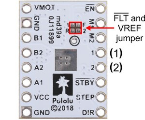
The STSPIN220 can detect several fault (error) states that it reports by driving its EN/FAULT pin low. The FAULT pin is not made available by default (to avoid conflicts when using the STSPIN220 carrier as a drop-in replacement for our other stepper motor driver carriers), but it can be connected to the pin labeled “(1)” or “(2)” by bridging the surface mount jumper labeled “F” on the bottom side of the board to the corresponding pad labeled “1” or “2”.
Current Limiting
https://youtu.be/89BHS9hfSUk
To achieve high step rates, the motor supply is typically higher than would be permissible without active current limiting. For instance, a typical stepper motor might have a maximum current rating of 1 A with a 5 Ω coil resistance, which would indicate a maximum motor supply of 5 V. Using such a motor with 10 V would allow higher step rates, but the current must actively be limited to under 1 A to prevent damage to the motor.
The STSPIN220 supports such active current limiting, and the trimmer potentiometer on the board can be used to set the current limit. You will typically want to set the driver’s current limit to be at or below the current rating of your stepper motor. One way to set the current limit is to put the driver into full-step mode and to measure the current running through a single motor coil without clocking the STEP input. The measured current will be equal to the current limit (since both coils are always on and limited to 100% of the current limit setting in full-step mode).
Another way to set the current limit is to measure the VREF voltage and calculate the resulting current limit. The VREF pin voltage is accessible via a small hole that is circled on the bottom silkscreen of the circuit board. The current limit relates to VREF as follows:
current limit=VREF×5 AV
Like the FAULT pin, VREF can be connected to the pin labeled “(1)” or “(2)” by bridging the surface mount jumper labeled “R” on the bottom side of the board to the corresponding pad labeled “1” or “2”.
Note: The coil current can be very different from the power supply current, so you should not use the current measured at the power supply to set the current limit. The appropriate place to put your current meter is in series with one of your stepper motor coils. If the driver is in full-step mode, both coils will always be on and limited to 100% of the current limit setting as (unlike some other drivers that limit it to about 70% in full-step mode). If your driver is in one of the microstepping modes, the current through the coils will change with each step, ranging from 0% to 100% of the set limit.
Power dissipation considerations
The driver ICs have maximum current ratings higher than the continuous currents we specify for these carrier boards, but the actual current you can deliver depends on how well you can keep the IC cool. The carrier’s printed circuit board is designed to draw heat out of the IC, but to supply more than the specified continuous current per coil, a heat sink or other cooling method is required.
This product can get hot enough to burn you long before the chip overheats. Take care when handling this product and other components connected to it.
Please note that measuring the current draw at the power supply will generally not provide an accurate measure of the coil current. Since the input voltage to the driver can be significantly higher than the coil voltage, the measured current on the power supply can be quite a bit lower than the coil current (the driver and coil basically act like a switching step-down power supply). Also, if the supply voltage is very high compared to what the motor needs to achieve the set current, the duty cycle will be very low, which also leads to significant differences between average and RMS currents. Additionally, please note that the coil current is a function of the set current limit, but it does not necessarily equal the current limit setting as the actual current through each coil changes with each microstep and can be further reduced if Active Gain Control is active.
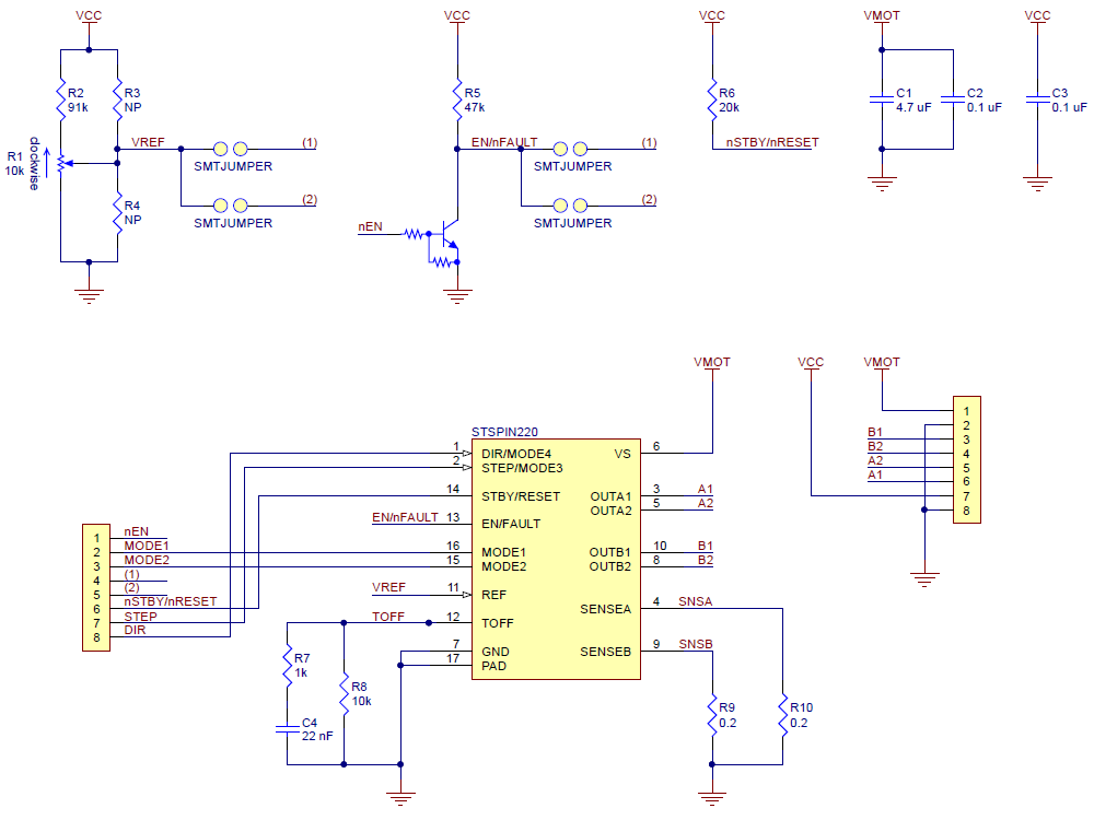
Schematic diagram