


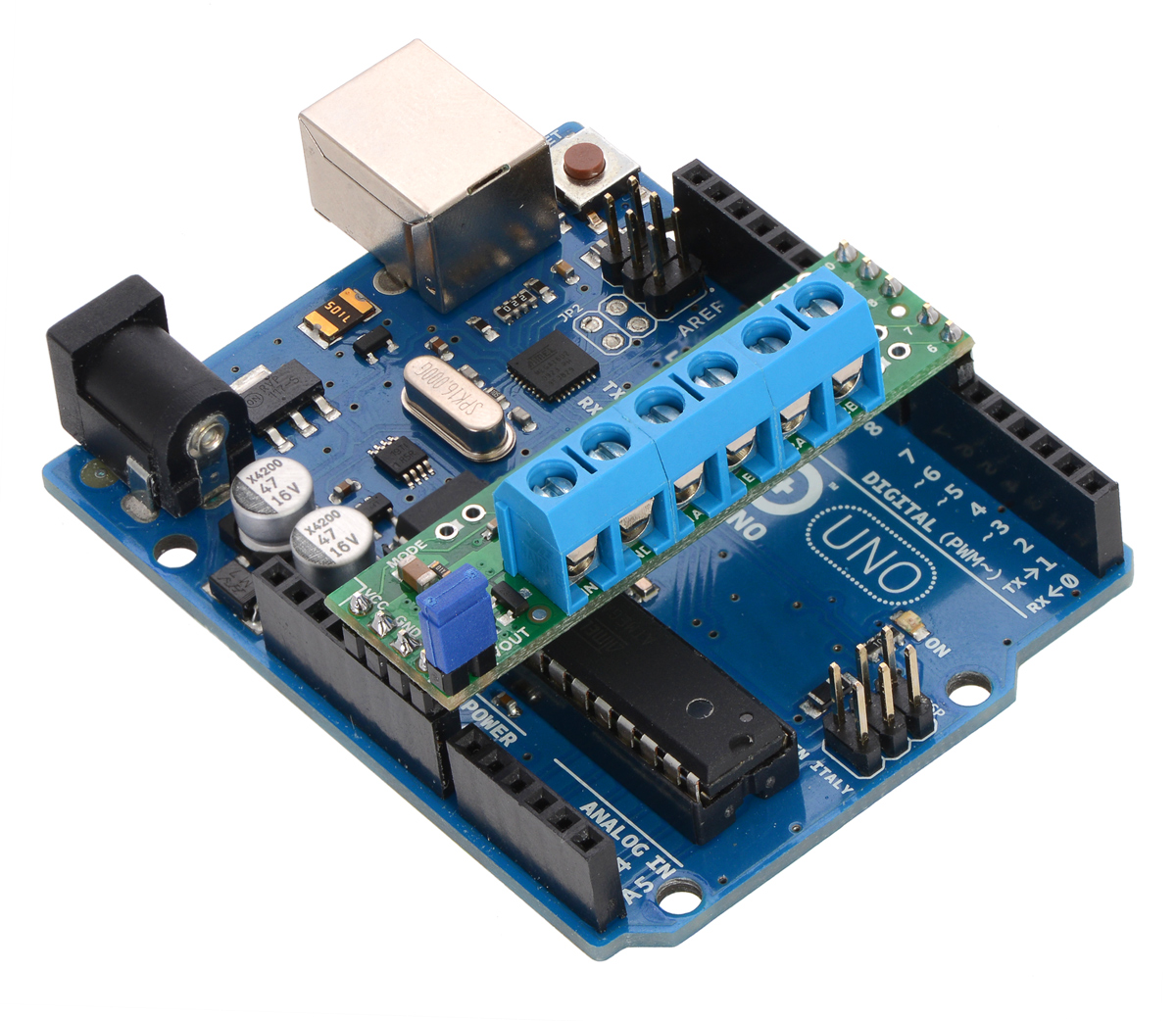
This small shield is an easy, economical way to control two small brushed DC motors with an Arduino or Arduino-compatible board. Its integrated DRV8835 dual motor driver allows it to operate from 1.5 V to 11 V, making it a great control option for low-voltage motors. The shield can deliver a continuous 1.2 A (1.5 A peak) per motor, or a continuous 2.4 A (3 A peak) to a single motor when configured with both channels connected in parallel.
This motor driver shield and its corresponding Arduino library make it easy to control a pair of bidirectional, brushed DC motors with an Arduino or compatible board, such as the A-Star 32U4 Prime. The board features Texas Instruments’ DRV8835 dual H-bridge motor driver IC, which allows it to operate from 1.5 V to 11 V and makes it particularly well suited for driving small, low-voltage motors. The shield can deliver a continuous 1.2 A per channel and tolerate peak currents up to 1.5 A per channel for a few seconds, and the channels can be optionally configured to run in parallel to deliver twice the current to a single motor. The shield ships fully populated with its SMD components, including the DRV8835 driver and a FET for reverse battery protection; header pins for interfacing with an Arduino and terminal blocks for connecting motors and power are included but are not soldered in (see the Assembly with included hardware section below).
|
|
The shield uses digital pins 7, 8, 9, and 10 for its control lines, though the control pin mappings can be customized if the defaults are not convenient. It should be compatible with any board that has a standard Arduino pin arrangement and the ability to generate PWM signals on pins 9 and 10. Compatible control boards include:
- A-Star 32U4 Prime
- Arduino Uno
- Arduino Leonardo
- Arduino Due
- Arduino Mega 2560
This shield is intended to provide a low-cost, basic motor driver option for Arduinos, so it is much smaller than typical Arduino shields and does not include pass-through, stackable headers. For higher-power drivers with more configuration options, see our larger MC33926 and VNH5019 motor driver shields.
For a higher-voltage alternative to this shield, please consider the A4990 dual motor driver shield. We also have a similarDRV8835 motor driver kit for the Raspberry Pi, as well as a smaller DRV8835 carrier (and an even smaller single-channelDRV8838 carrier) for those using a different controller or with tighter space constraints.
Although the DRV8835 itself works with a minimum motor supply voltage of 0 V, this shield’s reverse-protection circuit limits the minimum to 1.5 V. If a lower motor supply voltage is required, please consider using ourDRV8835 carrier with motor power supplied through the VMM pin.
 |
|
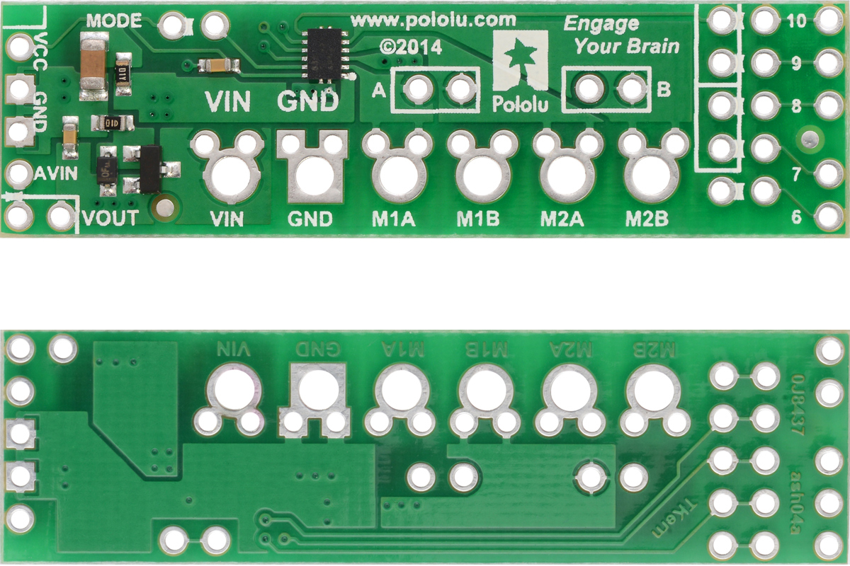
Pololu DRV8835 Dual Motor Driver Shield for Arduino, top and bottom sides. |
|---|
Features
- Dual-H-bridge motor driver: can drive two DC motors or one bipolar stepper motor
- Motor supply voltage: 1.5 V to 11 V
- Logic supply voltage 2 V to 7 V
- Output current: 1.2 A continuous (1.5 A peak) per motor
- Motor outputs can be paralleled to deliver 2.4 A continuous (3 A peak) to a single motor
- PWM operation up to 250 kHz (ultrasonic frequencies allow for quieter motor operation)
- Two possible interface modes: PHASE/ENABLE (default – one pin for direction, another for speed) or IN/IN (outputs mostly mirror inputs)
- Shield can optionally power the Arduino base directly when motor supply voltage is suitable
- Arduino library makes it easy to get started using this board as a motor driver shield
- Arduino pin mappings can be customized if the default mappings are not convenient
- Reverse-voltage protection on motor power supply
- Under-voltage lockout and protection against over-current and over-temperature
Assembly with included hardware
Before the shield can be plugged into your Arduino, header pins must be mounted to the bottom of the board (the side without any components or text) by soldering them into the appropriate holes. The shield ships with a 15-pin 0.1″ straight breakaway male header strip that can be broken into smaller pieces and used for this purpose. Four holes along the left side of the board (VCC, GND, GND, and AVIN) and all five holes along the right side of the board (digital pins 6 – 10) should be assembled with male header pins so that the shield will make the appropriate connections to the Arduino. Once assembled, one easy way to ensure that you are plugging the shield properly into the Arduino is to align the gap between pins 7 and 8 on the shield with the gap between pins 7 and 8 on the Arduino’s female headers.
|
|

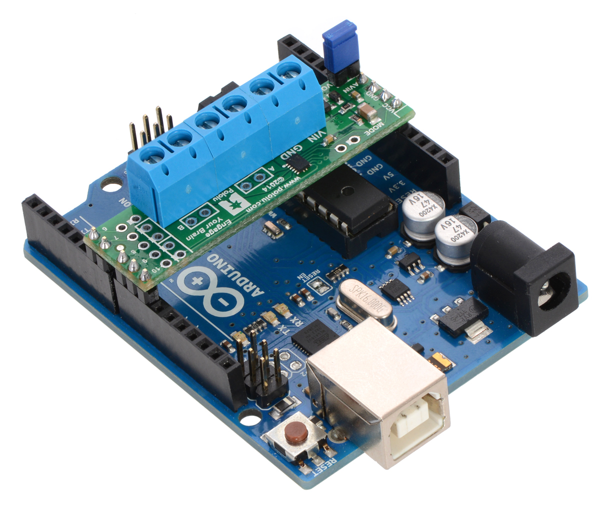
If you want the option of powering the Arduino from the shield, you can solder two male header pins to the lower-left corner of the board (in the silkscreen box next to the VOUT label). These pins should point up, away from the Arduino. If you then place the included blue shorting block across these pins (as shown in the above assembled picture), reverse-protected shield power will power the Arduino through it’s VIN pin. See the Using the shield section below for more information on this, including some important warnings.
Three 2-pin, 5 mm terminal blocks are included for making easy motor and power connections to the shield once they have been slid together and soldered to the six large through-holes. Alternatively, you can solder 0.1″ male header pins to the smaller through-holes above the terminal block holes, or you can just solder wires directly to the shield.
Additional shorting blocks and header pins beyond what is included can be used to make some of the more advanced optional modifications to the shield, such as remapping the control pins or paralleling the outputs.
An Arduino is not included.
Using the shield
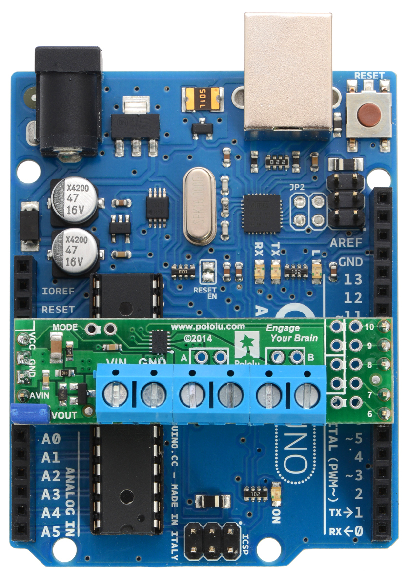
The shield plugs into Arduino digital pins 6, 7, 8, 9, and 10 on one side and Arduino VIN, GND, GND, and 5V/VCC on the other. The upper-left corner of the shield partially blocks the Arduino’s 3.3V pin, but this region of the board (marked with a white silkscreen box) can be removed if necessary to allow access. The shield also blocks Arduino digital pin 6, but it provides alternate access points to this pin via the neighboring through-holes. The board does not use pin 6 for anything.
In the shield’s default state, the motor driver shield and Arduino are powered separately, though they share a common ground and the Arduino’s 5V rail serves as the shield’s logic supply. When used this way, the Arduino must be powered via USB, its power jack, or its VIN pin, and the shield must be supplied with 1.5 V to 11 V through its large VIN and GND pads. Attempting to power the shield from the Arduino is not recommended as this could result in large currents flowing through small traces. However, if the motor power supply is suitable, it is possible to power the Arduino from the shield. This can be accomplished by placing a jumper between the shield pins in the lower-left corner labeled VOUT and AVIN, which connects the reverse-protected motor supply voltage to the Arduino’s VIN pin to power the Arduino. The Arduino’s power jack must remain disconnected at all times in this configuration.
Warning: When powering the Arduino from the motor shield, you must never connect a different power supply to the Arduino’s VIN pin or plug a power supply into the Arduino’s power jack, as doing so will create a short between the shield’s power supply and the Arduino’s power supply that could permanently damage both the Arduino and the motor shield. In this case, it is also important that your shield power supply is an acceptable voltage for your Arduino, so the full shield operating voltage range of 1.5 V to 11 V probably will not be available. For example, the recommended operating voltage of the Arduino Uno is 7 – 12 V.
By default, the board operates in PHASE/ENABLE mode, in which a PWM signal applied to the ENABLE pin determines motor speed and the digital state of the PHASE pin determines direction of motor rotation. Arduino pins 9 and 7 are used to control the speed and direction, respectively, of motor 1, and pins 10 and 8 control the speed and direction of motor 2. The table below shows how the inputs affect the outputs in this mode:
| Drive/brake operation in default PHASE/ENABLE mode | ||||
|---|---|---|---|---|
| xPHASE | xENABLE | MxA | MxB | operating mode |
| 0 | PWM | PWM | L | forward/brake at speed PWM % |
| 1 | PWM | L | PWM | reverse/brake at speed PWM % |
| X | 0 | L | L | brake low (outputs shorted to ground) |
PHASE/ENABLE mode should be suitable for most applications.
Configuring the board for IN/IN mode
The operating mode of the driver is controlled by the MODE pin, which the shield connects to VCC by default to select PHASE/ENABLE mode. To change the mode, locate the pair of 0.1″ through-holes in the upper-left part of the board labeled “MODE” and use a knife to cut the trace that connects the two on the bottom side of the PCB. Since the MODE pin has an internal pull-down resistor, severing its connection to VCC is all it takes to switch the control interface to IN/IN, which allows for slightly more advanced control options as described in the table below:
| Drive/coast or drive/brake operation with MODE=0 (IN/IN) | ||||
|---|---|---|---|---|
| xIN1 | xIN2 | MxA | MxB | operating mode |
| 0 | 0 | OPEN | OPEN | coast (outputs off) |
| PWM | 0 | PWM | L | forward/coast at speed PWM % |
| 0 | PWM | L | PWM | reverse/coast at speed PWM % |
| 1 | PWM | PWM | L | forward/brake at speed 100% − PWM % |
| PWM | 1 | L | PWM | reverse/brake at speed 100% − PWM % |
| 1 | 1 | L | L | brake low (outputs shorted to ground) |
Once the trace between the two pins has been cut, you can use a pair of header pins and a shorting block to control the mode: with the shorting block on, the mode is PHASE/ENABLE; with it off, the mode is IN/IN.
IN/IN mode is generally only useful if you only care about on/off control of the motors or if you can supply PWM signals to all four inputs, which is not possible when using the default pins on an Arduino Uno. If you want to be able to control the speed of the motors when using this mode, you should either remap the control pins or select an Arduino that can generate PWM signals with digital pins 7, 8, 9, and 10 (like the Arduino Mega 2560).
Configuring the board for single-channel mode (parallel outputs)
In order to use the two motor channels in parallel to control a single motor, it is important to ensure that both channels will always receive the same control signals, so the reconfiguration process begins with a modification to the control inputs. First, locate the 2×5 grouping of 0.1″ through-holes along the right side of the board. These holes run parallel to pins 6-10 and the traces between them on the underside of the PCB effectively link the Arduino pins to the DRV8835 control pins. If you want to remap one of these control pins, you can cut the desired trace with a knife and then run a wire from the inner hole to a new Arduino pin. The remapping for single-channel mode requires you cut one PWM (9 or 10) and one DIR (7 or 8) trace; cut 10 and 8 to control both outputs from the motor 1 input pins, or cut 9 and 7 to control both from the motor 2 input pins. If you then solder a row of header pins along the interior row of holes, you can safely connect both PWM lines together and both DIR lines together using shorting blocks. In this configuration, the two uncut Arduino control lines determine the behavior of both motor channels.
The last step is to connect the output channels together. An easy way to do this is to solder header pins to the two pairs of holes labeled “A” and “B” near the motor outputs. Placing shorting blocks across these pairs of pins connects M1A to M2A and M1B to M2B, which in turn means you can get up to 3 A from the connection points for either channel (e.g. you can have your motor connected just to the M1A and M1B terminal blocks rather than trying to find a way to connect it to all four motor outputs).
Real-world power dissipation considerations
The DRV8835 datasheet recommends a maximum continuous current of 1.5 A per motor channel. However, the chip by itself will overheat at lower currents. For example, in our tests at room temperature with no forced air flow, the chip was able to deliver 1.5 A per channel for approximately 15 seconds before the chip’s thermal protection kicked in and disabled the motor outputs, while a continuous current of 1.2 A per channel was sustainable for many minutes without triggering a thermal shutdown. The actual current you can deliver will depend on how well you can keep the motor driver cool. The carrier’s printed circuit board is designed to draw heat out of the motor driver chip, but performance can be improved by adding a heat sink. Our tests were conducted at 100% duty cycle; PWMing the motor will introduce additional heating proportional to the frequency.
This product can get hot enough to burn you long before the chip overheats. Take care when handling this product and other components connected to it.
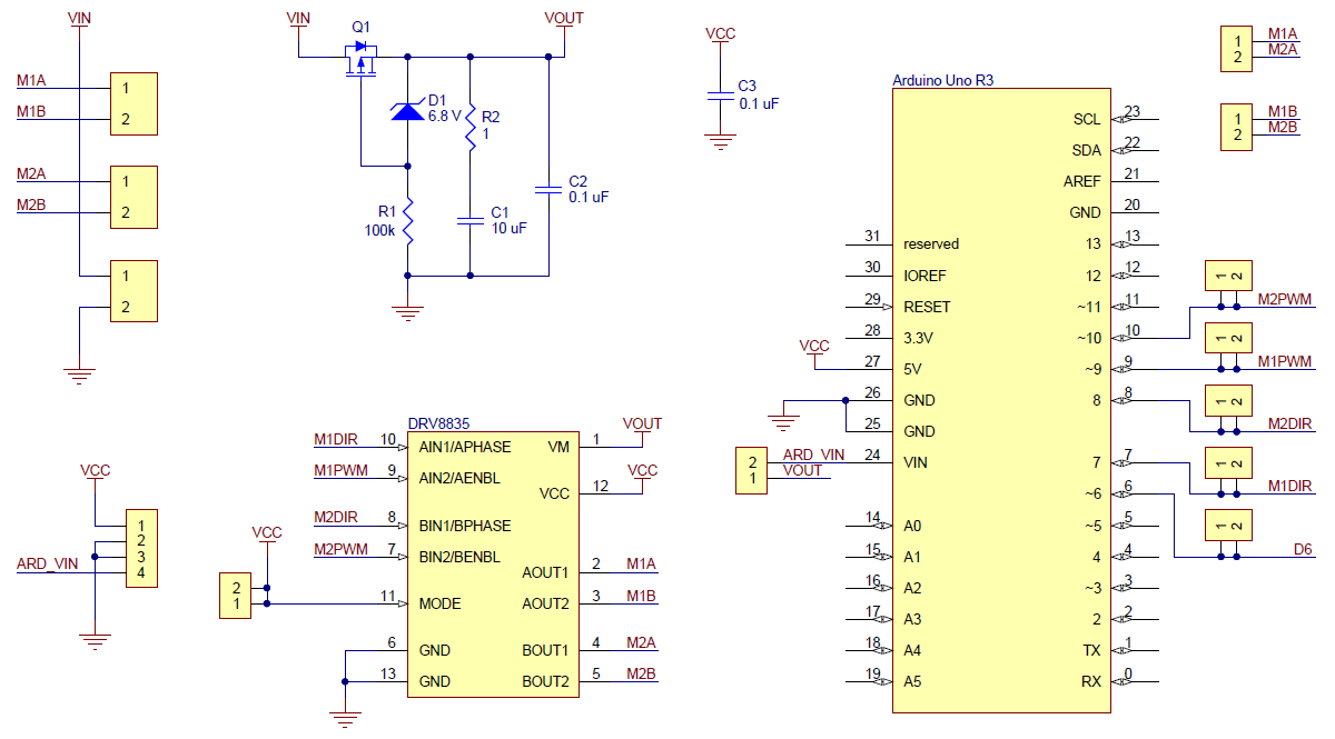
Schematic diagram
 |
|
Pololu DRV8835 Dual Motor Driver Shield for Arduino schematic diagram. |
|---|
This schematic is also available as a downloadable pdf (214k pdf).
Dimensions
| Size: | 2.0″ × 0.56″1 |
|---|---|
| Weight: | 2.3 g1 |
General specifications
| Motor driver: | DRV8835 |
|---|---|
| Motor channels: | 2 |
| Minimum operating voltage: | 1.5 V2 |
| Maximum operating voltage: | 11 V |
| Continuous output current per channel: | 1.2 A3 |
| Peak output current per channel: | 1.5 A |
| Continuous paralleled output current: | 2.4 A3 |
| Maximum PWM frequency: | 250 kHz |
| Reverse voltage protection?: | Y |
Notes:
- 1
- Without included hardware.
- 2
- The DRV8835 itself has a minimum motor supply voltage of 0 V, but the board's reverse-voltage protection circuit limits the minimum to 1.5 V.
- 3
- Typical results with 100% duty cycle at room temperature.
-
File downloads
- Pololu DRV8835 Dual Motor Driver Shield for Arduino schematic diagram (214k pdf)
- Printable schematic diagram for the Pololu DRV8835 Dual Motor Driver Shield for Arduino.
- Texas Instruments DRV8835 motor driver datasheet (1MB pdf)
Recommended links
- Arduino library for the Pololu DRV8835 Dual Motor Driver Shield
- This library for the Arduino makes it easy to interface with Pololu’s DRV8835 Dual Motor Driver Shield and drive a pair of brushed DC motors. It has been explicitly tested with the Uno R3, Leonardo, Mega 2560 R3, Due, and Duemilanove (ATmega328P). A sample sketch is included with the library. This library can also be used with ourDRV8835 Dual Motor Driver Carrier if it is connected to the appropriate pins on an Arduino.
- Texas Instruments DRV8835 product page
- Texas Instruments product page for the DRV8835, where you can find the latest datasheet and additional resources.
| Electrical Specifications | |
| Output Current | Continuous output current per channel: 1.2 A |
| Minimum Operating Voltage | 1.5 V |
| Maximum Operating Voltage | 11V |
| Physical Attributes | |
| Weight | 2.3 g |
| Dimensions | 2.0″ × 0.56″ |
Related Products

L298N Motor Driver Board
The L298N driver module, using ST' L298N chip, can directly drive two 3-30V DC motor, and provide a ..
रo 216.67

DFRobot DRI0009 L298P 2A Motor Shield For Arduino
This DFRobot Arduino Compatible Motor Shield (2A) uses L298P chip which allow to drive two 7-12V DC..
रo 1,288.00

L298N - Dual Full Bridge Driver
The L298N is a high voltage, high current, dual full bridge driver designed to accept standard TTL l..
रo 150.00

Seeed Studio L298 Dual H-Bridge Motor Driver - 105990007
Double H driver module uses ST L298N dual full-bridge driver, an integrated monolithic circuit in a ..
रo 2,651.58

Stepper Motor Driver A4988
A4988 is a complete microstepping motor driver with built-in translator for easy operation. This pro..
रo 155.56

DFRobot DRI0001 2x1A DC Motor Shield for Arduino
1A Motor Shield for Arduino This Motor shield for Arduino uses L293 chip which allow t..
रo 1,469.00 रo 1,548.00

Stepper Motor Driver - Easy Driver A3967
Each Easy Driver can drive up to about 750mA per phase of a bi-polar stepper motor. It defaults to 8..
रo 233.33

Pololu 2134 / 2874 DRV8834 Low-Voltage Stepper Motor Driver Carrier
This is a breakout board for TI’s DRV8834 microstepping bipolar stepper motor driver. It has a pinou..
रo 815.00

Pololu 2971 DRV8880 Stepper Motor Driver Carrier
This breakout board for TI’s DRV8880 microstepping bipolar stepper motor driver features adjustable ..
रo 286.00

Pololu Dual 2755/2756 MC33926 Motor Driver for Raspberry Pi
This add-on board enables a Raspberry Pi B+, A+, Pi 2, or Pi 3 to drive a pair of bru..
रo 3,875.37

Pololu 1213 Dual MC33926 Motor Driver Carrier
This dual brushed DC motor driver, based on Freescale’s MC33926 full H-bridge, has a wide operating ..
रo 3,608.32

Pololu 1212 MC33926 Motor Driver Carrier
This breakout board for Freescale’s MC33926 full H-bridge has an operating range of 5 – 28 V and can..
रo 1,712.04

Pololu 2130 DRV8833 Dual Motor Driver Carrier
This tiny breakout board for TI’s DRV8833 dual motor driver can deliver 1.2 A per channel continuous..
रo 898.00

Pololu 2135 DRV8835 Dual Motor Driver Carrier
This tiny breakout board for TI’s DRV8835 dual motor driver can deliver 1.2 A per channel conti..
रo 570.00

Pololu 2990 DRV8838 Single Brushed DC Motor Driver Carrier
This tiny breakout board for TI’s DRV8838 motor driver can deliver a continuous 1.7 A (1.8 A peak) t..
रo 405.76

Pololu 2961 MAX14870 Single Brushed DC Motor Driver Carrier
This compact breakout board for Maxim’s MAX14870 motor driver offers a wide operating voltage range ..
रo 979.21

Pololu 2960 BD65496MUV Single Brushed DC Motor Driver Carrier
This compact breakout board for ROHM’s BD65496MUV motor driver offers an operating voltage range of ..
रo 1,233.82

Pololu 2136 DRV8801 Single Brushed DC Motor Driver Carrier
This tiny breakout board for TI’s DRV8801 provides a modern alternative to classic motor drivers suc..
रo 1,341.00

Pololu 1112 Qik 2s12v10 Dual Serial Motor Controller
This powerful motor controller allows variable speed and direction control of two large, brushed DC ..
रo 7,908.00

Pololu 1110 Qik 2s9v1 Dual Serial Motor Controller
This small, inexpensive motor controller allows variable speed and direction control of two small, b..
रo 1,867.00

L298 Dual H-Bridge Motor Driver Module
New L298 Dual H-Bridge Motor Driver Features: Working mode: H bridge ..
रo 261.11

Pololu 3113 A-Star 32U4 Prime SV
The A-Star 32U4 Prime SV is a programmable board based on Atmel’s ATmega32U4 microcontroller and arr..
रo 3,404.41

Pololu 2753 DRV8835 Dual Motor Driver Kit for Raspberry Pi
This compact expansion board plugs directly into the GPIO header on a Raspberry Pi B+, Pi A+, Pi 2, ..
रo 1,225.56

ULN2003 Stepper Motor Driver Board
ULN2003 Stepper Motor Driver Board A B C D four-phase LED indicates the status of the ..
रo 82.22

Pololu 1392/1394 Jrk 21v3 USB Motor Controller with Feedback
The jrk 21v3 motor controller is a highly configurable brushed DC motor controller that supports fou..
रo 6,461.22

Pololu 767 TReX Jr Dual Motor Controller DMC02
This lower-power, smaller, and lower-cost version of the TReX is the ultimate general-purpose motor ..
रo 7,402.04

Pololu 2968 / 2969 Stepper Motor Driver Carrier, Digital Current Control MP6500
This product is a carrier board or breakout board for the MP6500 stepper motor driver from Monolithi..
रo 814.61

Pololu 2966 / 2967 Stepper Motor Driver Carrier, Potentiometer Current Control MP6500
This product is a carrier board or breakout board for the MP6500 stepper motor driver from Monolithi..
रo 815.31

Pololu 707/708 VNH2SP30/VNH3SP30 Dual Motor Driver Carrier MD03A 708 707
The Pololu dual high-power motor drivers are compact carriers for the VNH3SP30 and VNH2SP30 motor dr..
रo 10,687.76

DFRobot DRI0017 Gravity: 2x2A Motor Shield for Arduino Twin
Arduino product family is a great learning platform for electronics, programming and robotics. But m..
रo 1,301.00