


This carrier board for ST’s VNH5019 motor driver IC operates from 5.5 to 24 V and can deliver a continuous 12 A (30 A peak). It works with 2.5 to 5 V logic levels, supports ultrasonic (up to 20 kHz) PWM, and features current sense feedback (an analog voltage proportional to the motor current). Along with built-in protection against reverse-voltage, over-voltage, under-voltage, over-temperature, and over-current, these features make this product a great general-purpose motor driver.
This module is a compact breakout board for ST’s high-power VNH5019 motor driver IC, a fully integrated H-bridge that can be used for bidirectional speed control of a single brushed DC motor. The basic operation of the driver is summarized below, but we also recommend careful reading of the VNH5019 datasheet (475k pdf) before using this product. The board incorporates most of the components of the typical application diagram on page 14 of the VNH5019 datasheet, including pull-up and current-limiting resistors and a FET for reverse battery protection. It ships fully populated with its SMD components, including the VNH5019, as shown in the product picture.
Features :
- Operating voltage: 5.5 – 24 V
- Output current: 12 A continuous (30 maximum)
- 3V-compatible inputs
- PWM operation up to 20 kHz, which is ultrasonic and allows for quieter motor operation
- Current sense output proportional to motor current (approx. 140 mV/A)
- Motor indicator LEDs (indicates what the outputs are doing even when no motor is connected)
-
Robust:
- Reverse-voltage protection to -16 V
- Can survive input voltages up to 41 V
- Undervoltage and overvoltage shutdown
- High-side and low-side thermal shutdown
- Short-to-ground and short-to-Vcc protection
1 While the overvoltage protection typically kicks in at 27 V, it can trigger at voltages as low as 24 V, so we do not recommend using this motor driver with 24 V batteries, which significantly exceed 24 V when fully charged.
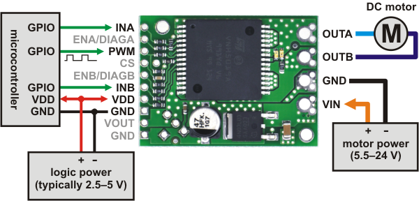
Using the Motor Driver : The motor and motor power connections are on one side of the board and the control connections are on the other side. The motor power supply connects to the large VIN and GND pins; it should be between 5.5 and 24 V and have the ability to deliver the potentially high currents the motor will require. The logic power supply (typically 2.5 – 5 V) connects to the small VDD and GND pads on the control side of the board and is used to power the internal pull-ups on the ENA and ENB enable lines. Any control input voltage above 2.1 V is guaranteed to be high, so this driver can be directly interfaced into both 3.3 and 5 V systems.
The following diagram shows the minimum connections required for interfacing this motor driver with a microcontroller:
 |
|
Minimal wiring diagram for connecting a microcontroller to a VNH5019 motor driver carrier. |
|---|
In this configuration, motor direction is determined by the states of the INA and INB pins and motor speed is controlled by the duty cycle of a PWM signal supplied to the driver’s PWM pin. The PWM pin is pulled low on the board, so the motor driver outputs are effectively disabled by default; the INA and INB pins are floating (they are not pulled to any particular default voltage). See the truth tables in the VNH5019A-E datasheet for more information on how the INA, INB, and PWM pins affect the driver outputs, OUTA and OUTB. Note that it is also possible to save a microcontroller I/O line by directly PWMing the INA and INB pins while holding the PWM pin high (e.g. by connecting it directly to VDD), but the trade-off is that this only works at low frequencies (a few hundred Hertz or less).
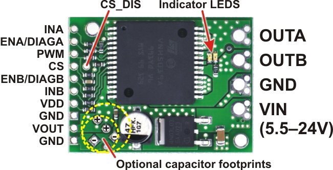
This board features motor indicator LEDs that can be used to test that motor driver outputs are working as expected before actually connecting a motor (this can be especially helpful in detecting problems due to insufficient power supplies). The LED brightness with increase with motor speed, and the LED color changes with direction.
Pinout
 |
| PIN | Default State | Description |
| VIN | The connection point for the positive side of the 5.5 – 24 V motor power supply. Since the overvoltage protection can be as low as 24 V, we do not recommend using 24V batteries for VIN. | |
| VDD | The connection point for the positive side of the logic power supply (typically 2.5 – 5 V). The only function of this pin is to power the internal pull-ups on the two enable lines, ENA and ENB. | |
| VOUT | This pin gives you access to the motor power supply after the reverse-voltage protection MOSFET (see the board schematic below). It can be used to supply reverse-protected power to other components in the system, but it should not be used for high currents. This pin should only be used as an output. | |
| GND | Ground connection points for logic and motor power supplies. The control source and the motor driver must share a common ground. | |
| OUTA | Output of half-bridge A (connects to one terminal of a DC motor). | |
| OUTB | Output of half-bridge B (connects to the other terminal of a DC motor). | |
| PWM | LOW | Pulse width modulation input: a PWM signal on this pin corresponds to a PWM output on the motor outputs. |
| INA | FLOAT | Motor direction input A (“clockwise” input). |
| INB | FLOAT | Motor direction input B (“counterclockwise” input). |
| CS | Current sense output. The pin voltage is roughly 140 mV per amp of output current when the CS_DIS pin is low or disconnected. The current sense reading is more accurate at higher currents. The CS pin is designed for PWM frequencies of 5 kHz or higher. If you use a PWM frequency lower than 5 kHz and want to measure the current, we recommend adding an extra capacitor between the CS pin and GND to smooth out the signal. For example, if you use a PWM frequency of 490 Hz and want to measure the current, you should add a 1 µF capacitor (or larger) between CS and GND. (Note that while the CS voltage can potentially exceed 3.3 V at high currents, the current sense circuit should be safe for use with many 3.3V analog inputs. Most MCUs have integrated protection diodes that will clamp the input voltage to a safe value, and since the CS circuit has a 10 kΩ resistor in series with the output, only a few hundred microamps at most will flow through that diode.) | |
| ENA/DIAGA | HIGH | Combination enable input/diagnostic output for half-bridge A. When the driver is functioning normally, this pin acts as an enable input, with a logical high enabling half-bridge A and a logical low disabling half-bridge A. When a driver fault occurs, the IC drives this pin low and half-bridge A is disabled. This pin is connected to VDD through a pull-up resistor on the board. |
| ENB/DIAGB | HIGH | Combination enable input/diagnostic output for half-bridge B. See the description of ENA/DIAGA. |
| CS_DIS | LOW | Disables the current sense output, CS, when high. Can be left disconnected in most applications. |
Included Hardware
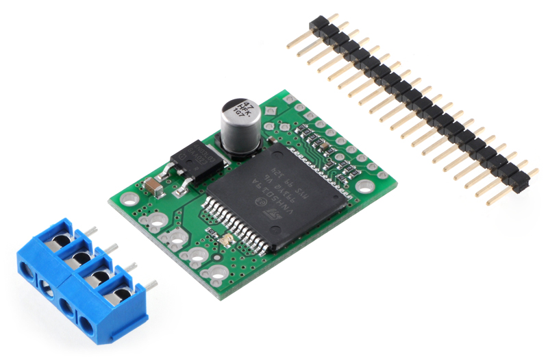
A 20-pin 0.1″ straight breakaway male header and two 2-pin 5mm terminal blocks are included with the motor driver as shown in the picture below. You can use the terminal blocks to make your motor and motor power connections, or you can break off an 8×1 section of the 0.1″ header strip and solder it into the smaller through-holes that border the four large motor and motor power pads. Note, however, that the terminal blocks are only rated for 16 A, and each header pin pair is only rated for a combined 6 A, so for higher-power applications, thick wires should be soldered directly to the board.
 |
|
VNH5019 motor driver carrier with included hardware. |
|---|
Soldering the 0.1″ headers to the logic connections enables use with custom cables or solderless breadboards, or wires can be soldered directly to the board for more compact installations. Motor and motor power connections should not be made through a breadboard.
The motor driver includes a 47 uF electrolytic power capacitor, and there is room to add additional capacitors (e.g. to compensate for long power wires or increase stability of the power supply). Additional power capacitors are usually not necessary, and no additional capacitors are included with this motor driver.
The two mounting holes are intended for use with #2 screws (not included).
Schematic Diagram
 |
|
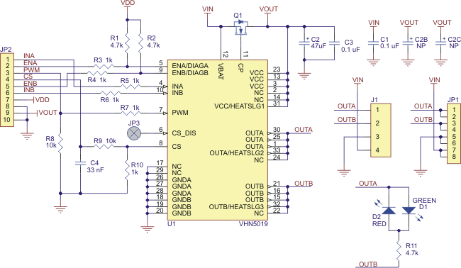
Schematic diagram for the Pololu VNH5019 motor driver carrier. |
|---|
This schematic is also available as a downloadable pdf: VNH5019 carrier schematic (34k pdf)
Note: All boards shipped from Pololu prior to October 28, 2011 have 1.5k current sense resistors (R10 in the schematic above), which results in a current sense (CS) output of approximately 210 mV/A. That resistor has now been changed to 1k for better compatibility with 3V systems, producing a CS output of approximately 140 mV/A.
VNH3SP30, VNH2SP30, and VNH5019 Comparison
 |
|
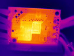
Thermal image of the underside of the VNH5019 motor driver carrier during one of our current tests. |
|---|
The current-related values in the table below (i.e. the entries to which footnote 3 applies) are the results of tests on only one or two of each driver version, so they do not capture potential unit-to-unit variation. As such, the values should be treated as rough estimates of performance, not as performance guarantees. While these tests seem to indicate that the VNH2SP30 runs a bit cooler—and hence can deliver more continuous current—than the VNH5019, it is important to note that the three driver versions were tested at different times under potentially different conditions, so the results are not necessarily accurate indications of relative performance.
In our tests, we noticed that the thermal protection on the VNH5019 was activating at a lower temperature (153°C) than on the VNH2SP30 (170°C), which could partially account for the shorter VNH5019 overheating times. However, we also observed that the VNH5019 was reaching slightly higher temperatures than the VNH2SP30 when used under the same conditions: the VNH5019 reached a temperature of 85°C after 3 minutes at 10 A while the VNH2SP30 reached a temperature of 80°C.
The following table offers a comparison of the three drivers:
| VNH3SP30 | VNH2SP30 | VNH5019 | |
| Operating voltage: | 5.5 – 16 V | 5.5 – 16 V | 5.5 – 16 V |
Related Products

L298N Motor Driver Board
The L298N driver module, using ST' L298N chip, can directly drive two 3-30V DC motor, and provide a ..
रo 216.67

DFRobot DRI0009 L298P 2A Motor Shield For Arduino
This DFRobot Arduino Compatible Motor Shield (2A) uses L298P chip which allow to drive two 7-12V DC..
रo 1,288.00

L298N - Dual Full Bridge Driver
The L298N is a high voltage, high current, dual full bridge driver designed to accept standard TTL l..
रo 150.00

Pololu 2993 H2 High-Power Motor Driver 36v11 CS
This discrete MOSFET H-bridge motor driver enables bidirectional control of one high-power DC brushe..
रo 5,143.35