
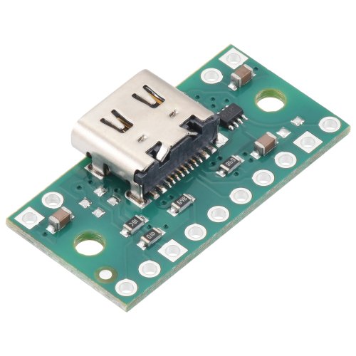
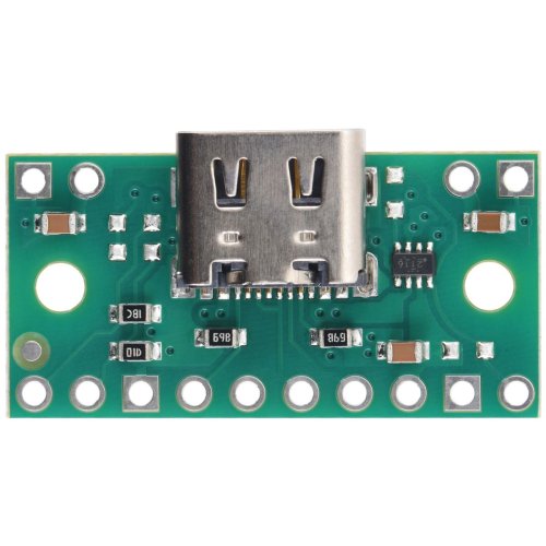
This carrier board for Texas Instruments’s TPS2116 power multiplexer allows seamless switching between two power sources of 1.6 V to 5.5 V with up to 2.5 A of continuous current while blocking reverse current into either source. By default, the mux selects the higher of the two input voltages, and it can also be configured to switch from the VIN1 supply to the VIN2 supply on command or when VIN1 falls below a preset voltage. In addition
The Texas Instruments TPS2116 power multiplexer allows seamless switching between two power sources of 1.6 V to 5.5 V with up to 2.5 A of continuous current while blocking reverse current into either source. The power multiplexer (or mux) has an adjustable switching threshold that helps reduce output voltage droop when switching. Each input channel is controlled by an internal MOSFET switch, so the mux avoids the voltage drop that occurs when diodes are used to OR multiple power supplies together. Our TPS2116 carriers break out all of the chip’s features to 0.1″-spaced pins, making it easy to use with standard solderless breadboards. In addition, each board serves as a breakout for a USB Type-C connector that can be used to supply one of the input power rails.
By default, the TPS2116 automatically selects the power source that has a higher voltage, but the board can be configured to prioritize VIN1 as the selected source until it falls below a configurable switching threshold. A common application of these multiplexers is enabling a device to be powered by USB or an external power supply, automatically choosing the appropriate source based on what is connected. We offer two versions of these TPS2116 boards that differ in how the USB 5 V supply (VBUS) is connected and whether it is preferred when the board is used in priority mode:
- Item #3728 (usb09a) connects VBUS to VIN1 (the USB power source is preferred in priority mode).
- Item #3729 (usb09b) connects VBUS to VIN2 (the non-USB power source (VIN1) is preferred in priority mode).
Since these boards are carriers for the TPS2116, we recommend careful reading of the TPS2116 datasheet.
Details for item #3729
This version of the TPS2116 carrier, usb09b, connects VBUS to VIN2 so that the non-USB power source (VIN1) has priority when the board is used in priority mode.
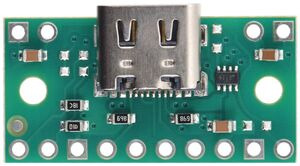
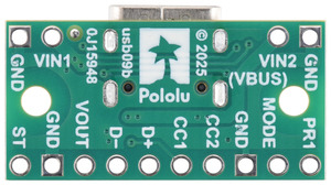
- Using the power multiplexer
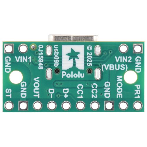
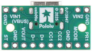
- Pinout
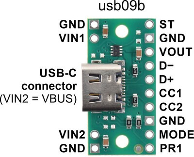
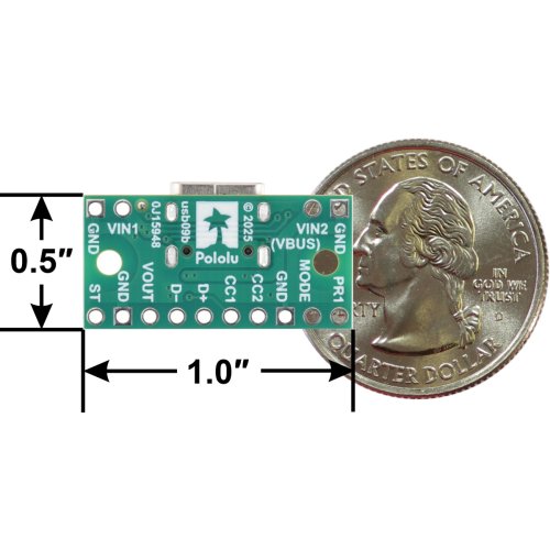
The board’s through-holes are arranged with a 0.1″ spacing for compatibility with solderless breadboards and 0.1″-pitch headers. The board has two mounting holes that work with #2 and M2 screws.
Details for item #3728
This version of the TPS2116 carrier, usb09a, connects VBUS to VIN1 so that the USB power source has priority over VIN2 when the board is used in priority mode.
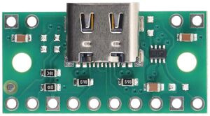
- Using the power multiplexer
- Pinout
Control inputs
The MODE and PR1 pins can be used to override the default behavior of the TPS2116.
The MODE pin determines the operating mode of the device. The board pulls this pin low by default, which results in autoswitching mode (sometimes called diode mode): the higher of the two input sources is automatically selected (connected to VOUT).
However, when MODE is high, the selected input source is controlled by the PR1 pin instead: a voltage on PR1 above 1 V causes VIN1 to be selected (connected to VOUT), while a PR1 voltage below 1 V selects VIN2. You can drive the PR1 pin from an external source, such as an output pin from a microcontroller, to directly control the multiplexer’s switching (manual mode). Alternatively, the precise nature of the PR1 pin’s 1 V threshold makes it possible to use an external resistor to set a desired switching threshold for VIN1. By tying MODE to VIN1 (or otherwise driving it high) and connecting this external resistor between PR1 and VIN1, a voltage divider is created with the on-board 15 kΩ PR1 pull-down resistor, and the board will operate in priority mode, selecting VIN1 as long as the output of this voltage divider is greater than 1 V. (If PR1 drops below the 1 V threshold, the multiplexer switches to VIN2 regardless of whether VIN2 is lower or higher than VIN1.) The value of the added resistor determines the voltage at which the behavior of the multiplexer changes, as defined by the following equation:
Vthreshold=(R15 kΩ+1)⋅1 V
For 5 V applications, adding a 47 kΩ resistor works well, since that sets the threshold to about 4.13 V.
If PR1 is driven high while MODE is low, the TPS2116 turns off the output and enters a low-power shutdown state.
Power connections without USB
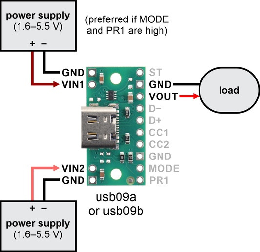
If you want to select from between two general power supplies, you can connect one power source across VIN1 and GND and the other across VIN2 and GND. The voltages on these power inputs can be 1.6 V to 5.5 V. The load should be connected across VOUT and GND and should draw no more than 2.5 A. In this configuration, the power supply connected to VIN1 is the preferred power source if MODE and PR1 are high. (Note that both versions of the TPS2116 board behave the same in applications without USB; they differ only in which input is connected to the USB 5 V supply.)
Power connections with USB
The Type-C USB connector makes it easy to use USB as one of the two power sources. On this board (usb09b), the VBUS line from the USB connector is tied to VIN2. This allows you to power your circuit from either USB or an external power source connected to VIN1, with VIN1 as the preferred power source if MODE and PR1 are high.
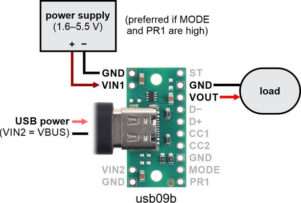
If you want USB to be preferred instead of the external source, consider item #3728 (usb09b) instead.
Warning: It is important to be aware that while this board might appear to have three power inputs, two of those three are tied together (there are only two independent power inputs to the TPS2116). As such, you must take care to avoid creating a short circuit between USB power and an external power supply. For example, if you use this version with USB connected, any external power supply must be connected to VIN1; connecting it to VIN2 will create a short between this power supply and USB power.
Other usage considerations
This TPS2116 carrier board includes a 4.7μF capacitor on each of the two power inputs (VIN1 and VIN2). However, we strongly recommend adding additional capacitance to each input (an electrolytic capacitor of at least 33 μF is a good starting point) if you are switching more than a few hundred milliamps of current or if your power leads are longer than about 6 inches (150 mm). Otherwise, the rapid switching of current can cause LC voltage spikes that are much higher than the input voltage, and if these spikes exceed the maximum voltage rating of the TPS2116 (6 V), the chip can be destroyed.
If the TPS2116 switches between power sources while the load is drawing substantial current, the new source’s voltage might drop with the applied load while the old source’s voltage rises as the load is removed. If this happens in priority mode with PR1 connected to a voltage divider on VIN1, the changing voltages could make PR1 cross the 1 V threshold again, and the multiplexer might start switching between the two inputs repeatedly (exacerbating the previously-mentioned LC spikes). To mitigate this behavior, you can add hysteresis to the switchover threshold by connecting an additional resistor between PR1 and ST. For example, with a divider on PR1 that includes a 47 kΩ pull-up and a 15 kΩ pull-down, adding a 1 MΩ resistor adds about 50 mV of hysteresis. This Microsoft Excel-based tool from TI can help calculate an appropriate hysteresis resistor for other scenarios (use the sheet named “TPS2116”).
Finally, additional capacitance on VOUT can help reduce how much the output voltage drops while the TPS2116 switches. The board includes a 4.7μF capacitor on VOUT, but high-current applications might benefit from 100 μF or more of extra capacitance.
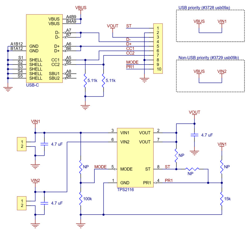
Schematic diagram:
Package Includes:
- 1 x Pololu 3729 / 3728 TPS2116 Power Multiplexer Carrier with USB Type-C Connector
Pololu 3729 / 3728 TPS2116 Power Multiplexer Carrier with USB Type-C Connector
- Brand:: Pololu
- Product Code: :Pololu-TPS2116-Power-Multiplexer
- Reward Points: :4
- Availability: :In Stock
-
रo 406.12
- Price in reward points: 406
-
- 25 or more रo 387.76
- 100 or more रo 373.47
- 250 or more रo 360.20
Available Options
Related Products
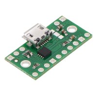
Pololu 2596 TPS2113A Power Multiplexer Carrier with USB Micro-B Connector
This breakout board for Texas Instruments’s TPS2113A autoswitching power multiplexer allows you to s..
रo 815.31
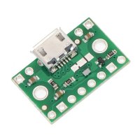
Pololu 2594 FPF1320 Power Multiplexer Carrier with USB Micro-B Connector
This breakout board for Fairchild’s FPF1320 acts as a power multiplexer, allowing you to select whic..
रo 370.41
Tags: Pololu, Power Multiplexer, Carrier, USB, Type-C