This breakout board for TI’s DRV8434S microstepping bipolar stepper motor driver operates from 4.5 V to 48 V and can deliver up to approximately 1.2 A continuous per phase without a heat sink or forced air flow (2 A peak). The SPI interface allows configuration of the current limit, step mode (11 step modes from full-step through 1/256-step), decay mode, and stall detection. The driver also features built-in protection against under-voltage, over-current, and over-temperature conditions. This version of the board uses an on-board potentiometer for setting the maximum current limit, and SPI can be used to set the actual current limit to intermediate values in increments of the set maximum/16.

This version of our DRV8434S SPI Stepper Motor Driver Carrier, Potentiometer for Max. Current Limit ships with male header pins installed as shown in the main product picture, so no soldering is required to use it with an appropriate 16-pin socket or solderless breadboard. Please see the DRV8434S SPI Stepper Motor Driver Carrier, Potentiometer for Max. Current Limit product page for more information about the driver.
Available Options:
  • DRV8434S SPI Stepper Motor Driver Carrier, Potentiometer for Max. Current Limit with connector not soldered 
  • DRV8434S SPI Stepper Motor Driver Carrier, Potentiometer for Max. Current Limit with connector soldered 
Overview:
This product is a carrier board or breakout board for the DRV8434S stepper motor driver from Texas Instruments (TI); we therefore recommend careful reading of the DRV8434S datasheet before using this product. This stepper motor driver lets you control one bipolar stepper motor at up to approximately 1.2 A continuous per phase without a heat sink or forced air flow (see the Power dissipation considerations section below for more information).
This version of our DRV8434S SPI Stepper Motor Driver Carrier, Potentiometer for Max. Current Limit ships with male header pins installed as shown in the main product picture, so no soldering is required to use it with an appropriate 16-pin socket or solderless breadboard. Please see the DRV8434S SPI Stepper Motor Driver Carrier, Potentiometer for Max. Current Limit product page for more information about the driver.

Features:
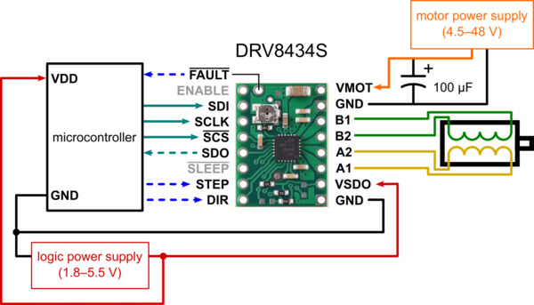
  • 4.5 V to 48 V supply voltage range
  • Can deliver up to 1.2 A continuous per phase without additional cooling (2 A peak)
  • Can interface directly with 1.8 V, 3.3 V, and 5 V systems
  • Highly configurable through SPI interface
  • Optional STEP/DIR control pins (stepping can also be controlled through SPI interface alone)
  • Eleven different step resolutions: full-step with 100% current, full-step with 70% current, non-circular 1/2-step, 1/2-step, 1/4-step, 1/8-step, 1/16-step, 1/32-step, 1/64-step, 1/128-step, 1/256-step
  • Eight configurable decay modes, including smart tune dynamic decay and ripple control modes
  • Two current limit control options available, each with two header pin assembly options, making four versions in all:
  • Potentiometer for Max. Current Limit: an on-board potentiometer sets the maximum current limit up to 2 A, and the actual current limit can be scaled down through SPI
  • with header pins included but not soldered
  • with header pins soldered
  • 2A Max. Current Limit: the maximum current limit is fixed at 2A and the actual current limit is set solely through SPI in increments of 125 mA
  • with header pins included but not soldered
  • with header pins soldered
  • Integrated stall detection
  • Over-temperature thermal shutdown, over-current protection, open load detection, under-voltage lockout, and charge pump over-voltage protection
  • Driver IC integrates spread spectrum clocking of its internal oscillator and charge pump for reduced EMI
  • 4-layer, 2 oz copper PCB for improved heat dissipation
  • Exposed solderable ground pad below the driver IC on the bottom of the PCB
  • This product ships with all surface-mount components—including the DRV8434S driver IC—installed as shown in the product picture.
  • We also have a variety of other stepper motor driver options in this same form factor with different operating profiles and features.
Note: This driver needs to be enabled and configured through its SPI interface on power up, so your microcontroller must be capable of acting as an SPI master (either with an SPI peripheral or software SPI).
Some unipolar stepper motors (e.g. those with six or eight leads) can be controlled by this driver as bipolar stepper motors. For more information, please see the frequently asked questions. Unipolar motors with five leads cannot be used with this driver.
Details for item #3766/3767

This version of the DRV8434S Stepper Motor Driver Carrier uses an on-board trimmer potentiometer to set the maximum current limit. Header pins are included but not soldered (see item #3767 for a version of this carrier with header pins already installed). For a version with a fixed 2 A maximum current limit see item #3768.
Included hardware
The DRV8434S stepper motor driver carrier ships with one 1×16-pin breakaway 0.1″ male header. The headers can be soldered in for use with solderless breadboards or 0.1″ female connectors. You can also solder your motor leads and other connections directly to the board.
Using the driver:

Power connections:
The driver requires a motor supply voltage of 4.5 V to 48 V to be connected across VIN and GND. This supply should be capable of delivering the expected stepper motor current. Note that supply voltages below 6 V limit the maximum settable current limit; see the Current limiting section for more details. The VSDO pin must also be supplied with the desired SPI logic voltage. The SPI interface on the DRV8434S is compatible with 1.8 V, 3.3 V, and 5 V systems.

Warning:
We have observed that if the DRV8434S’s VSDO pin is left floating while VM is connected, VSDO can briefly output a pulse of voltage when nSLEEP changes state. Since our board pulls nSLEEP up to VSDO, this pulse can cause nSLEEP to briefly go high and then low again, causing more pulses and leading to an abnormal oscillating voltage on both pins.

To avoid this unwanted behavior, we recommend that you avoid disconnecting VSDO and nSLEEP (or allowing them to float) while VM is present. (One way to be safe is to always disconnect motor power before disconnecting logic power.)
Motor connections:
Four, six, and eight-wire stepper motors can be driven by the DRV8434S if they are properly connected; a FAQ answer explains the proper wirings in detail.
Warning:
Connecting or disconnecting a stepper motor while the driver is powered can destroy the driver. (More generally, rewiring anything while it is powered is asking for trouble.)
Step (and microstep) size:
Stepper motors typically have a step size specification (e.g. 1.8° or 200 steps per revolution), which applies to full steps. A microstepping driver such as the DRV8434S allows higher resolutions by allowing intermediate step locations, which are achieved by energizing the coils with intermediate current levels. For instance, driving a motor in quarter-step mode will give the 200-step-per-revolution motor 800 microsteps per revolution by using four different current levels.
The microstep resolution is configured through the SPI interface. For the microstep modes to function correctly, the current limit must be set low enough (see below) so that current limiting gets engaged. Otherwise, the intermediate current levels will not be correctly maintained, and the motor will skip microsteps.
Control inputs and status outputs:
While the DRV8434S allows control of a stepper motor through a simple step and direction interface, it must first be enabled and configured through its SPI interface after each power-up. This means that the controlling microcontroller must be capable of acting as an SPI master (either with an SPI peripheral or software SPI), and it must be connected to the SDI, SCLK, and SCS pins. While the SDO and FAULT pins are not required to use this driver, it is generally a good practice to use them to monitor for error conditions.
The rising edge of each pulse to the STEP input corresponds to one microstep of the stepper motor in the direction selected by the DIR pin. These inputs are both pulled down by default. If you just want rotation in a single direction, you can leave DIR disconnected. Stepping and direction can also both be controlled solely through SPI.
The chip has two different inputs for controlling its power states: SLEEP and ENABLE. For details about these power states, see the datasheet. SLEEP is connected to VSDO through a 10k pull-up resistor and ENABLE is internally pulled high by the chip. Since both pins are pulled up, they can both be left disconnected or dynamically controlled by connecting them to a digital output of an MCU.
The DRV8434S also features an open-drain FAULT output that drives low whenever the driver detects an under-voltage, over-current, open load, stall detection, or thermal shutdown fault. FAULT is pulled up to VSDO on the board, so no external pull-up resistor is needed.
Note:
The open load, over-current protection, and over-temperature shutdown faults are latching by default and must be cleared with the CLR_FLT bit, a SLEEP reset pulse, or a power cycle. The latching behavior of these faults can be reconfigured using the SPI interface.
Current limiting:
To achieve high step rates, the motor supply is typically higher than would be permissible without active current limiting. For instance, a typical stepper motor might have a maximum current rating of 1 A with a 5 Ω coil resistance, which would indicate a maximum motor supply of 5 V. Using such a motor with 9 V would allow higher step rates, but the current must actively be limited to under 1 A to prevent damage to the motor.

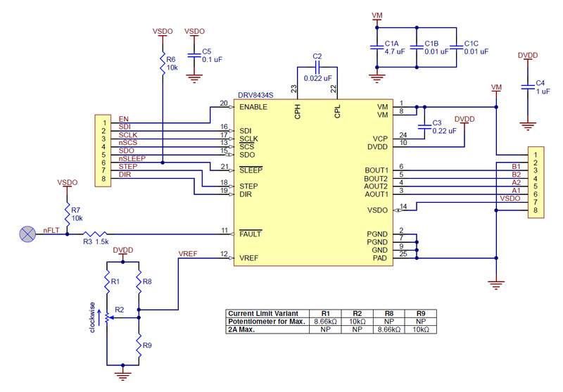
The DRV8434S supports such active current limiting. The trimmer potentiometer on the board can be used to set the maximum current limit, and the TRQ_DAC bits can be used to scale that maximum current limit by a configurable percentage. For example if the potentiometer is turned all the way clockwise to achieve a 2 A maximum limit and TRQ_DAC = 0b0000 (100%), the effective current limit will be 2 A. If the potentiometer is left at the maximum and TRQ_DAC = 0b1111 (6.25%), the effective current limit will be 125 mA. This is useful for adjusting the motor current on the fly, and by decreasing the current when less torque is needed you can save power and reduce heat dissipation.

Before using the driver, we recommend setting the maximum current limit at or below the current rating of your stepper motor with the current scalar at its default of 100%. One way to set the maximum current limit is to put the driver into full-step 100% current mode and then measure the current running through a single motor coil without clocking the STEP input.

Another way to set the current limit is to measure the VREF voltage and calculate the resulting current limit. The VREF pin voltage is accessible via a small hole that is circled on the bottom silkscreen of the circuit board. The current limit in amps relates to the reference voltage in volts as follows:

Max. Current Limit=VREF1.32   or   Effective Current Limit=VREF ⋅ TRQ_DAC_%1.32
or, rearranged to solve for VREF:

VREF=Max. Current Limit⋅1.32   or   VREF=Effective Current Limit⋅1.32TRQ_DAC_%
So, the effective current limit in amps (A) is equal to the VREF voltage in volts (V) times the current scalar (TRQ_DAC) percentage divided by 1.32, and if you have a stepper motor rated for 1 A, for example, you can set the current limit to about 1 A by setting the reference voltage to about 1.32 V and leaving TRQ_DAC at 100%.

When the driver ships, the current limit potentiometer will not be set at the 2A maximum of the driver, or any other specific setting. It must be manually set as described above before using the driver. We also carry a version of the DRV8434S with a set 2 A maximum current limit and no potentiometer where the effective current limit is set solely through SPI.

For input voltages below 6 V, the DRV8434S’s internally regulated logic voltage VDVDD linearly drops from 5 V with a 6 V input to around 4.35 V with a 4.5 V input. VDVDD supplies the potentiometer circuit used to set the driver’s current limit, so using supply voltages below 6 V reduces the maximum current limit setting possible with the onboard potentiometer. With an input of 4.5 V, the maximum settable current limit is 1.75 A.
Note: The coil current can be very different from the power supply current, so you should not use the current measured at the power supply to set the current limit. The appropriate place to put your current meter is in series with one of your stepper motor coils. If the driver is in full-step 100% current or full-step 71% current modes, both coils will always be on and limited to 100% or 71% of the current limit setting respectively. If your driver is in one of the microstepping modes, the current through the coils will change with each step, ranging from 0% to 100% of the set limit. See the DRV8434S datasheet for more information.
Power dissipation considerations:
The DRV8434S carrier has a maximum current rating of 2 A per coil, but the actual current you can deliver depends on how well you can keep the IC cool. The carrier’s printed circuit board is designed to draw heat out of the IC, but to supply more than approximately 1.2 A per coil, a heat sink or other cooling method is required.
This product can get hot enough to burn you long before the chip overheats. Take care when handling this product and other components connected to it.

  • Please note that measuring the current draw at the power supply will generally not provide an accurate measure of the coil current. Since the input voltage to the driver can be significantly higher than the coil voltage, the measured current on the power supply can be quite a bit lower than the coil current (the driver and coil basically act like a switching step-down power supply). Also, if the supply voltage is very high compared to what the motor needs to achieve the set current, the duty cycle will be very low, which also leads to significant differences between average and RMS currents. Additionally, please note that the coil current is a function of the set current limit, but it does not necessarily equal the current limit setting as the actual current through each coil changes with each microstep.

Stall detection:

The DRV8434S driver can detect motor stall conditions or an end of travel by detecting back-EMF phase shift. An internal algorithm generates a measure of the phase shift called torque count which is independent of motor current, ambient temperature, and supply voltage. For a lightly loaded motor, the torque count will be a non-zero value. As the motor approaches a stall condition, torque count will approach zero. If the torque count falls below the stall threshold, the device will detect a stall. For details on using stall detection, please see the DRV8434S datasheet.
Please note that the DRV8434S’s stall detection has limitations, and how well it works will depend on the specifics of the application, including the choice of motor. In our tests, we have found it works better when the step signal is steady (e.g. provided by a microcontroller’s PWM timer output rather than software delays) and the speed is moderate. Here are some other considerations to be aware of:

  • The ideal stall threshold is a function of the speed, which can make it difficult to use this feature in applications with widely varying speeds. For applications with small speed changes, we recommend characterizing the stall threshold or doing the learning mode process at the lowest speed.
  • Stall detection might not work well at very low or very high speeds.
  • Stall detection might not work well for motors with high coil resistance.
  • Arduino library and example code
  • We have written a DRV8434S library for Arduino that provides basic functions for configuring and operating the driver using an Arduino or Arduino-compatible controller. The library includes several example sketches.
Schematic diagram:
          Schematic diagram of the DRV8434S SPI Stepper Motor Driver Carrier.
Package Includes:
  • 1 x DRV8434S SPI Stepper Motor Driver Carrier, Potentiometer for Max. Current Limit 

                                                    (OR)

  • 1 x DRV8434S SPI Stepper Motor Driver Carrier, Potentiometer for Max. Current Limit (Header Pins Soldered)

Write a review

Please login or register to review

Pololu 3766 / 3767 DRV8434S SPI Stepper Motor Driver Carrier, Potentiometer for Max. Current Limit

  • Brand: Pololu
  • Product Code:NR-Pololu-Stepper-Potentiometer
  • Reward Points:11
  • Availability:In Stock
  • रo 1,286.20

  • Ex Tax:रo 1,090.00
  • Price in reward points:1090

  • 13 or more रo 1,274.40
  • 27 or more रo 1,262.60
  • 65 or more रo 1,250.80
  • 130 or more रo 1,239.00

Available Options


Related Products

Pololu 2134 / 2874 DRV8834 Low-Voltage Stepper Motor Driver Carrier

Pololu 2134 / 2874 DRV8834 Low-Voltage Stepper Motor Driver Carrier

This is a breakout board for TI’s DRV8834 microstepping bipolar stepper motor driver. It has a pinou..

रo 767.00 Ex Tax:रo 650.00

Pololu 2966 / 2967 Stepper Motor Driver Carrier, Potentiometer Current Control MP6500

Pololu 2966 / 2967 Stepper Motor Driver Carrier, Potentiometer Current Control MP6500

This product is a carrier board or breakout board for the MP6500 stepper motor driver from Monolithi..

रo 671.42 Ex Tax:रo 569.00

Pololu 2133 / 2982 DRV8825 Stepper Motor Driver Carrier, High Current

Pololu 2133 / 2982 DRV8825 Stepper Motor Driver Carrier, High Current

This breakout board for TI’s DRV8825 microstepping bipolar stepper motor driver features adjustable ..

रo 2,385.96 Ex Tax:रo 2,022.00

Pololu 3768/3769 DRV8434S SPI Stepper Motor Driver Carrier, 2A Max. Current Limit

Pololu 3768/3769 DRV8434S SPI Stepper Motor Driver Carrier, 2A Max. Current Limit

This breakout board for TI’s DRV8434S microstepping bipolar stepper motor driver operates from 4.5 V..

रo 1,250.80 Ex Tax:रo 1,060.00

Pololu 3762 / 3763 DRV8434 Stepper Motor Driver Carrier

Pololu 3762 / 3763 DRV8434 Stepper Motor Driver Carrier

DRV8434 Stepper Motor Driver CarrierThis breakout board for TI’s DRV8434 microstepping bipolar stepp..

रo 960.52 Ex Tax:रo 814.00

Tags: Pololu, Stepper, Motor, Driver, Carrier, Potentiometer

The product is currently Out-of-Stock. Enter your email address below and we will notify you as soon as the product is available.

Name
Email
Phone
Comments