

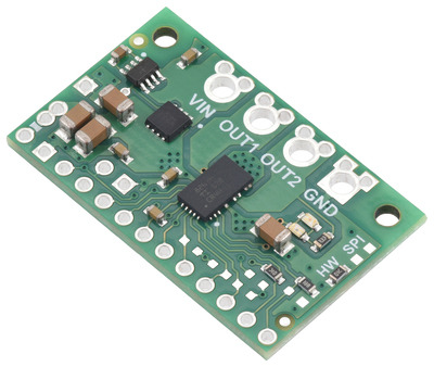
This breakout board for TI’s DRV8263H motor driver offers a wide operating voltage range of 4.5 V to 65 V and can deliver a continuous 3.5 A to a single bidirectional brushed DC motor. The DRV8263H also features integrated current sensing and regulation that limits the peak motor current to about 10 A by default, as well as built-in protection against under-voltage, over-current, and over-temperature. The carrier board adds protection against reverse voltage.
This product is a carrier board for Texas Instruments’ DRV8263H-Q1 brushed DC motor driver; we therefore recommend careful reading of the DRV8263H-Q1 datasheet before using this product.
Features:
- Drives a single bidirectional brushed DC motor or two unidirectional brushed DC motors
- Motor supply voltage: 4.5 V to 65 V
- Output current: up to approximately 3.5 A continuous (10 A default current limit); max continuous current depends on operating voltage, slew rate, PWM frequency, and ambient conditions
- Supports 3 V to 5 V logic voltage (5.5 V max)
- Integrated current sensing and adjustable active current regulation
- Three input control modes:
- Phase/enable (PH/EH)
- PWM (IN/IN)
- Independent half-bridge control
- Off-state diagnostics can be used to identify open or shorted load conditions
- Under-voltage lockout and protection against over-current and over-temperature
- Carrier board adds reverse-voltage protection
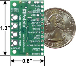
- Size: 0.8″ × 1.3″ (20.3 × 33 mm)
- Two 0.086″ mounting holes for #2 or M2 screws
Using the motor driver
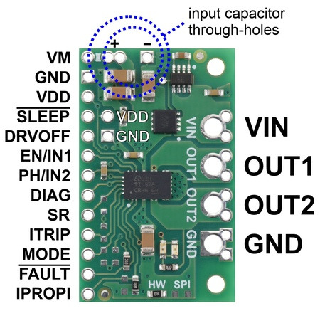
Pinout:
| Pin | Default state | Description |
|---|---|---|
| VIN | 4.5 V to 65 V board power supply input. | |
| GND | Ground connection points for the motor and logic supplies. | |
| VM | This pin gives access to the motor power supply after the reverse-voltage protection circuit (see the board schematic below). It can be used to supply reverse-protected power to other components in the system. | |
| OUT1 | Motor output 1. | |
| OUT2 | Motor output 2. | |
| SLEEP | LOW | Sleep input that puts the driver into a low-power sleep mode when low. The driver outputs are high-impedance (coast) in sleep mode. |
| DRVOFF | HIGH | Input that sets the driver outputs to high-impedance (coast) when high. |
| EN/IN1 | LOW | Motor control input 1 (functions as an enable pin in PHASE/ENABLE mode). |
| PH/IN2 | LOW | Motor control input 2 (functions as a direction pin in PHASE/ENABLE mode). |
| DIAG | FLOATING | Input for configuring load type indication and fault reaction. The state of this pin is latched during device initialization following power-up or wake-up from sleep. See the datasheet for more information. |
| SR | FLOATING | Input for configuring the slew rate. We recommend grounding this pin, which selects the fastest slew rate and maximizes the driver’s output current capabilities. The state of this pin is latched during device initialization following power-up or wake-up from sleep. See the datasheet for more information. |
| ITRIP | FLOATING | Input for configuring the driver’s optional internal load current regulation feature. The default setting results in a current regulation trip threshold of 3 V, which is reached at a current of 10 A with the default IPROPI current sensitivity of 300 mV/A. The state of this pin is not latched, and changes will take effect while the driver is operating. See the datasheet for more information. |
| MODE | FLOATING | Input for configuring the control mode. Leaving it floating (the default setting) selects PWM (IN/IN) control mode. Setting it low selects phase/enable (PH/EN) mode. Connecting it to ground through a 16 kΩ resistor selects independent half-bridge control mode. The state of this pin is latched during device initialization following power-up or wake-up from sleep. See the datasheet for more information. |
| FAULT | PULLED UP | Fault output. The carrier board pulls this pin to VDD through a 10 kΩ resistor, which sets it high by default. This pin drives low during a fault condition (e.g. over-current, over-temperature, or under-voltage). It is also an output for the driver’s off-state diagnostics, which can be used to identify open or shorted load conditions. See the datasheet for more information. |
| IPROPI | Current sense output. This pin provides an analog current-sense feedback voltage of approximately 300 mV/A by default. |
The motor and motor power (4.5 V to 65 V) connections are on one side of the board, and the control connections (3 V to 5 V logic supply) are on the other. There are two options for making the high-power connections (VIN, OUT1, OUT2, GND): large holes spaced 5 mm apart, which are compatible with the 5mm-pitch terminal blocks, and pairs of 0.1″-spaced holes that can be used with 0.1″ male headers and are compatible with perfboards, breadboards, and 0.1″ connectors. These holes are on the same 0.1″ grid as the control connections. You can also solder wires directly to the through-holes for more compact installations.
The driver is disabled by default, and enabling it requires setting SLEEP high and DRVOFF low. This can be done through general purpose digital outputs from the controlling device, which allows for dynamic control of these enable modes, or by tying the pins to the respective logic voltages that enable the driver, such as by jumpering them to the neighboring VDD and GND through-holes.
The DRV8263 features three possible control modes: phase/enable (PH/EN), PWM (IN/IN), and independent half-bridge. The MODE pin determines the control interface, and the state is latched when the driver is enabled through power-up or the SLEEP pin.
For better performance, we recommend installing a large capacitor across the motor supply and ground close to the motor driver. We generally recommend using a capacitor of at least a few hundred μF and rated well above the maximum supply voltage; the required capacitance will be greater if the power supply is poor or far (more than about a foot) from the driver, and it will also depend on other factors like motor characteristics and applied PWM frequency. A through-hole capacitor can be installed directly on the board in the holes labeled VM and GND on the silkscreen ('+' and '−' in the wiring diagram pictures below). The driver includes 8.8 µF of on-board ceramic capacitors, which might be sufficient for brief tests and limited low-power operation, but adding a bigger capacitor is recommended for most applications.
PWM (IN/IN) mode
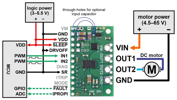
Minimal wiring diagram for connecting a microcontroller to a DRV8263H Single Brushed DC Motor Driver Carrier in PWM (IN/IN) control mode.
When the MODE pin is left floating, the driver is set to PWM (IN/IN) control mode. Use of this control mode generally requires two PWM signals to be supplied, one for each of the two IN pins. The following truth table shows how to achieve drive/coast (fast decay) and drive/brake (slow decay) operation using the IN/IN control interface:
| PWM control mode with MODE=floating (IN/IN) | ||||
|---|---|---|---|---|
| IN1 | IN2 | OUT1 | OUT2 | operating mode |
| 0 | 0 | H | H | brake high (outputs shorted to VM) |
| PWM | 0 | H | PWM (L/H) | forward/brake at speed PWM % |
| 0 | PWM | PWM (L/H) | H | reverse/brake at speed PWM % |
| PWM | 1 | inverted PWM (L/Z) | inverted PWM (H/Z) | reverse/coast at speed 100% − PWM % |
| 1 | PWM | inverted PWM (H/Z) | inverted PWM (L/Z) | forward/coast at speed 100% − PWM % |
| 1 | 1 | Z | Z | coast (outputs off) |
Phase/enable (PH/EN) mode
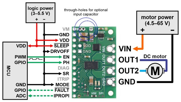
Minimal wiring diagram for connecting a microcontroller to a DRV8263H Single Brushed DC Motor Driver Carrier in phase/enable (PH/EN) control mode.
Advanced usage with independent half-bridge mode
When the MODE pin is connected to ground through a 16 kΩ resistor prior to enabling the driver, it is set to independent half-bridge control mode. See the DRV8263 datasheet for more information about this control mode.
Current sensing and limiting
The driver’s IPROPI pin outputs a voltage proportional to the motor current (measured through the high-side MOSFETs of the H-bridge). The output voltage is about 300 mV/A by default.
The DRV8263H-Q1 has the ability to limit the motor current through current chopping: once the IPROPI voltage reaches a set threshold, the driver goes into brake mode (slow decay) for about 30 µs before applying power to drive the motor again. This makes it more practical to use the driver with a motor that might only draw a few amps while running but can draw many times that amount when starting.
The current limit is affected by both the ITRIP configuration and the current sense sensitivity. By default, the current regulation trip threshold is 3 V; together with the default 300 mV/A sensitivity, this corresponds to a 10 A current limit. The threshold can be lowered by connecting ITRIP to ground through resistors as described in the datasheet, or current limiting can be disabled entirely by connecting ITRIP directly to ground (although the driver has separate overcurrent protection functionality that remains active). Alternatively, the current limit can be raised by lowering the current sense sensitivity through the addition of an external pull-down resistor on IPROPI in parallel with the 1.5 kΩ already on the board.
Real-world power dissipation considerations
The DRV8263H has overcurrent protection that kicks in at a minimum of 28 A, and the board is configured for a current limit of 10 A by default. However, the chip by itself will overheat at lower currents. In our tests, we found that the chip on our carrier board was able to deliver 10 A for less than a second before its thermal protection kicked in and disabled the motor outputs. The actual current you can deliver will depend on how well you can keep the motor driver cool. The shield’s printed circuit board is designed to help with this by drawing heat out of the motor driver chip.
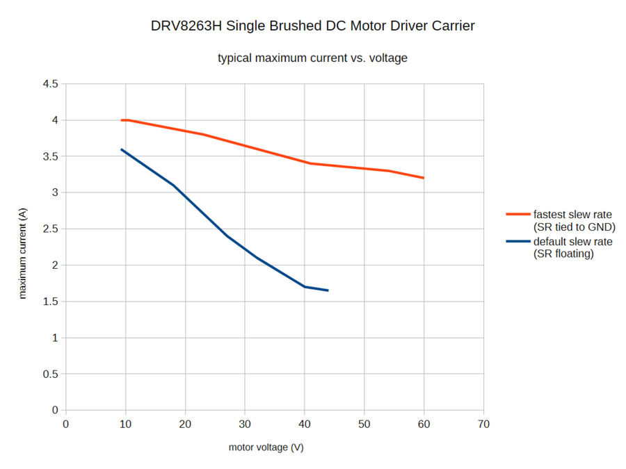
PWMing the motor will introduce additional heating proportional to the frequency, and the driver’s slew rate setting is also a factor here. For most applications, we recommend connecting the SR pin directly to ground (as shown in the minimal wiring diagrams above) to select the fastest slew rate on the DRV8263H. This graph shows the effect of the slew rate and motor voltage on the typical continuous maximum current sustainable by the driver:
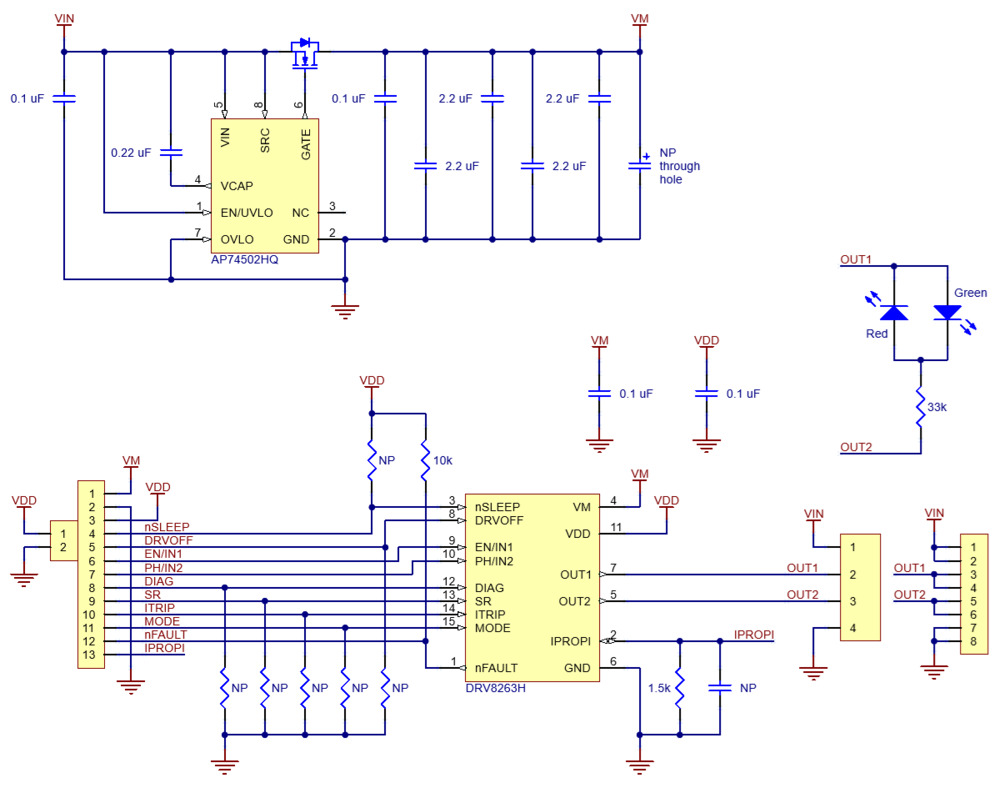
Schematic:
Package Includes:
- 1x Pololu 5238 DRV8263H Single Brushed DC Motor Driver Carrier
Related Products

Pololu 2990 DRV8838 Single Brushed DC Motor Driver Carrier
This tiny breakout board for TI’s DRV8838 motor driver can deliver a continuous 1.7 A (1.8 A peak) t..
रo 405.76

Pololu 2961 MAX14870 Single Brushed DC Motor Driver Carrier
This compact breakout board for Maxim’s MAX14870 motor driver offers a wide operating voltage range ..
रo 979.21

Pololu 2997 TB9051FTG Single Brushed DC Motor Driver Carrier
The TB9051FTG is an H-bridge motor driver IC that can be used for bidirectional control of a single ..
रo 1,061.22

Pololu 4039 DRV8256P Single Brushed DC Motor Driver Carrier
Texas Instruments’ DRV8256P is a tiny H-bridge motor driver IC that can be used for bidirectional co..
रo 1,263.85

Pololu 4733 MP6550 Single Brushed DC Motor Driver Carrier
This tiny breakout board for the MPS MP6550 motor driver offers a wide operating voltage range of 1...
रo 564.11

Pololu 5285 / 5286 MPQ6612A Single Brushed DC Motor Driver Carrier
This breakout board for the MPS MPQ6612A motor driver offers a wide operating voltage range of 4 V t..
रo 1,061.22
Tags: Pololu, DRV8263H, Single Brushed, DC Motor, Driver, Carrier