
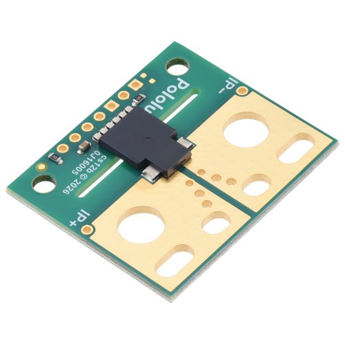
This is the large version of a simple carrier for Allegro’s ACS37200LLXTR-150B3/150B5 Hall effect-based, electrically isolated current sensor that offers an extra-low-resistance (~0.05 mΩ) IC current path, a 150 kHz bandwidth with <4 µs response time, and an overcurrent fault output with a user-configurable threshold.
We are offering these breakout boards with support from Allegro Microsystems as an easy way to use or evaluate their ACS37200 Hall effect-based, electrically isolated current sensors with user-configurable overcurrent fault output; we therefore recommend careful reading of the ACS37200 datasheet (1MB pdf) before using this product. The following list details some of the sensor’s key features:
Hall effect-based sensor with electrically isolated current path allows the sensor to be inserted anywhere along the current path and to be used in applications that require electrical isolation.
Extra-low primary current path resistance of 0.05 mΩ in the sensor IC for higher efficiency.
Differential Hall sensing rejects common-mode fields, so the orientation of the sensor relative to uniform external magnetic fields (e.g. the Earth’s magnetic field) has less effect on the measurement.
150 kHz bandwitdth analog output voltage proportional to AC or DC currents.
Less than 4 µs response time.
Output is not ratiometric (i.e. the zero point and sensitivity are independent of the actual supply voltage), which provides immunity from noisy supplies.
User-configurable overcurrent fault output with 3 µs response time indicates when the current magnitude exceeds the set threshold and can be used for fast short-circuit detection.
VREF output for pseudo-differential signaling in noisy application environments.
Integrated digital temperature compensation circuitry allows improved accuracy over the full operating temperature range.
Automotive-grade operating temperature range of -40°C to 150°C.
Carrier boards, available in compact and large sizes, include routed slots for increased creepage along the PCB surface and offer a variety of ways to insert it into the current path along with 0.1″-pitch (breadboard-compatible) power, ground, and output pins.
Optional connection points for convenient 4-wire measurement of the IC current path resistance.
The PCB is made with 2-layer (compact versions) or 6-layer (large versions) 2-oz copper, so very little power is lost in the module.
3.3V and 5V versions available.
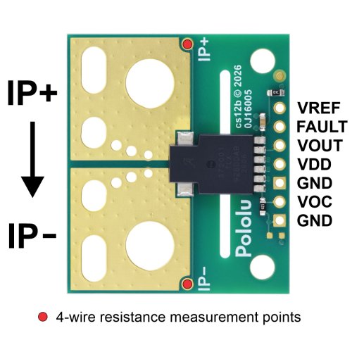
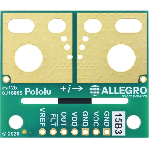
The connection points and the direction interpreted as positive current flow (via the +i arrow) are labeled on the silkscreen.
Details for item #5791/5795
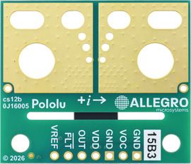
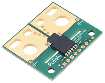
This large carrier features the ACS37200LLXTR-150B3, which is intended for nominal 3.3 V operation and is designed for bidirectional input current from -150 A to +150 A. This version can be visually distinguished from the other versions by the “15B3” printed on the bottom side, as shown in the left picture above.
This large carrier features the ACS37200LLXTR-200B5, which is intended for nominal 5 V operation and is designed for bidirectional input current from -200 A to +200 A. This version can be visually distinguished from the other versions by the “20B5” printed on the bottom side, as shown in the left picture above.
A compact carrier is also available for this sensor IC for more space-constrained applications or to evaluate the IC’s performance with a smaller PCB area and fewer copper layers for thermal dissipation.
Using the sensor
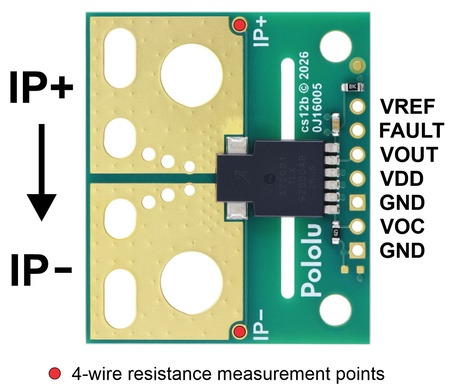
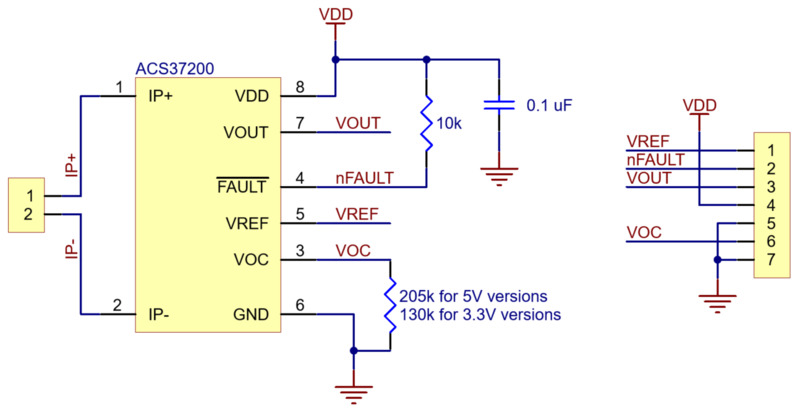
This sensor has five required connections: the input current (IP+ and IP-), logic power (VDD and GND), and the sensor output (VOUT).
The sensor requires a supply voltage of 3.15 V to 3.45 V to be connected across the VDD and GND pads, which are labeled on the bottom silkscreen. The sensor outputs an analog voltage on VOUT that is centered at 1.65 V and changes by 8.8 mV per amp of input current, with positive current increasing the output voltage and negative current decreasing the output voltage:
VOUT=1.65V+0.0088VA⋅IP
IP=VOUT–1.65V0.0088VA=(VOUT–1.65V)⋅114AV
The output is not ratiometric, so the zero point and sensitivity are independent of the actual supply voltage.
The zero-current reference voltage, which is available on VREF, can be used to reduce errors due to reference shifts or noise on the ground line.
The carrier board also includes two optional connection points, marked in red in the picture above, for taking a 4-wire measurement of the IC current path resistance. This is to more conveniently evaluate that property of the chip and is not required for normal use of this product as a current sensor.
Setting the overcurrent fault threshold
The optional VOC pin can be used to set the overcurrent fault threshold. An on-board 130 kΩ resistor between VOC and GND sets the default overcurrent fault threshold to approximately 200% of the nominal sensing range, and an external resistor can be added in parallel between VOC and GND to lower this threshold to between 50% and 200%. The following equation gives the value of this parallel resistor, ROC, in kΩ as a function of overcurrent fault threshold percentage P:
ROC=130kΩ⋅P197%–P
So for example, to set the overcurrent fault limit to 50% of the nominal sensing range, a 44 kΩ external resistor can be added between VOC and GND:
ROC=130kΩ⋅50%197%–50%≈44kΩ
As a shortcut, VOC can be connected directly to ground to set the overcurrent fault limit to 100% of the nominal sensing range.
The optional FAULT pin is normally at VDD and is pulled low when the IP current magnitude exceeds the set overcurrent fault threshold in either direction. This pin only asserts while the fault condition is present (it is not latched).
We manufacture these boards in-house at our Las Vegas facility, which gives us the flexibility to make these current sensors with custom default overcurrent fault thresholds. If you are interested in customization, please contact us.
Making connections to the board
We manufacture these boards in-house at our Las Vegas facility, which gives us the flexibility to make these current sensors with custom default overcurrent fault thresholds. If you are interested in customization, please contact us.
Making connections to the board
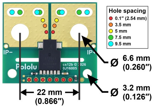
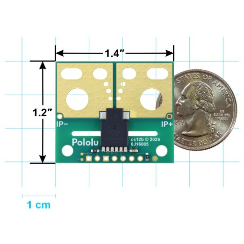
You can insert the board into your current path in a variety of ways. The largest through-holes are 6.6 mm in diameter with 22 mm spacing. These can be used with 1/4″ or M6 screws for attaching various types of lugs or solderless ring terminals, or thick wires up to 4 AWG can be soldered directly to the board. The slots near the edge of the board can accommodate a 4-pin terminal block or other connector with a pitch between 7.5 mm and 9.5 mm. Holes with 0.1″, 3.5 mm, and 5 mm spacing are also available as shown in the diagram above for connecting male header pins or terminal blocks, but please note that these connection options are generally not suitable for high currents and could limit the usable range of the sensor. The pictures below show examples of various connection options with the CT432/CT433 large carrier, which has the same physical dimensions as the ACS37200 large carrier.
The VREF, VOUT, VDD, and GND pins work with 0.1″-pitch header pins and are compatible with standard solderless breadboards
Isolation rating and board creepage considerations
The ACS37200 has a manufacturer-rated basic working isolation voltage of 1097 VRMS. The IC package has a creepage of 8 mm, and our large carrier PCB has a routed slot under the IC to provide a PCB creepage distance of 10.4 mm. A rough rule of thumb is that uncontaminated FR4 PCBs should have roughly 1 mm of creepage per 100 VRMS of isolation. Please note that these carrier boards are not certified to any particular safety standard.
Warning: This product is generally intended for use below 30 V, and many of the application example pictures (e.g. use on a breadboard) are appropriate for such lower-voltage applications. These boards can be used at higher voltages, but working with higher voltages can be extremely dangerous and should only be attempted by qualified individuals with appropriate equipment and experience.
Schematic and dimension diagrams
Documents:
Package Includes:
- 1 x Pololu 5791/5795 ACS37200LLXTR-150B3 Current Sensor Large Carrier -150A to +150A, 3.3V/5V
Related Products
Pololu 5783 ACS37200LLXTR-100B5 Current Sensor Compact Carrier -100A to +100A, 5V
This is the compact version of a simple carrier for Allegro’s ACS37200LLXTR-100B5 Hall effect-based,..
रo 1,811.30
Pololu 5782 ACS37200LLXTR-200B3 Current Sensor Compact Carrier -200A to +200A, 3.3V
This is the compact version of a simple carrier for Allegro’s ACS37200LLXTR-100B5 Hall effect-based,..
रo 1,811.30
Pololu 5792 / 5793 ACS37200LLXTR-200B3/100B5 Current Sensor Large Carrier -200A to +200A, 3.3V / -100A to +100A, 5V
We are offering these breakout boards with support from Allegro Microsystems as an easy way to use o..
रo 2,311.00
Tags: Pololu, ACS37200LLXTR, Current Sensor, Carrier